

Ha van egy hosszú szobád, folyosód vagy lépcsőd, és szeretnél egy lámpát három különböző helyről irányítani, amelyek a szoba két végén és a közepén helyezkednek el. Akkor valószínűleg az egyik leggyakrabban feltett és félreértett kérdést teszed fel a házi vezetékezéssel kapcsolatban. A válasz meglepő: az áramkör nem három három-utas kapcsolóval van bekötve. Ehelyett, amikor egy áramkört három helyről irányítanak, két 3-utas kapcsolóra van szükség az áramkör két végén, és egy négy-utas kapcsolóra, amelyet a két utazó vezeték segítségével kell csatlakoztatni. Ez a cikk mindent tárgyal a koncepcióval, szerszámokkal, a bekötés lépéseivel, a terminálok térképezésével, az ellenőrzési folyamattal és a specifikációkkal kapcsolatban, hogy elkerüljük az amatőrök által leggyakrabban elkövetett hibákat.
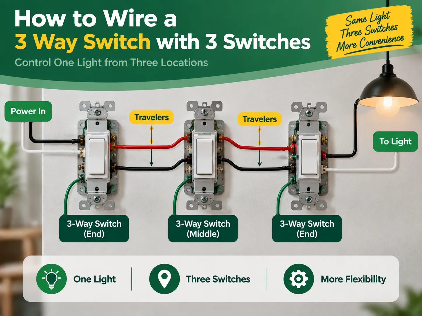
A válasz rövid: Egy lámpát három kapcsolóról irányítani csak két három-utas kapcsolóra és egy négy-utas kapcsolóra van szükség, nem három három-utas kapcsolóra. Az első három-utas kapcsoló a közös terminálján keresztül kapja a feszültséget, és a két utazó vezetéken keresztül küldi ki az áramot. A négy-utas kapcsoló a középen helyezkedik el, és a termináljain kapcsolja az utazókat. Az utolsó három-utas kapcsoló megkapja az utazó vezetékeket, és ismét a kapcsolt feszültséget küldi a lámpához. Tehát amikor a három kapcsoló közül az egyik be van kapcsolva, a lámpa ki- vagy bekapcsol, függetlenül a többi kapcsoló helyzetétől. Ki kell kapcsolnod az áramot az elektromos megszakítóból, ellenőrizd egy teszterrel, címkézd fel megfelelően minden vezetéket, és kövesd az alábbi ábrákat.
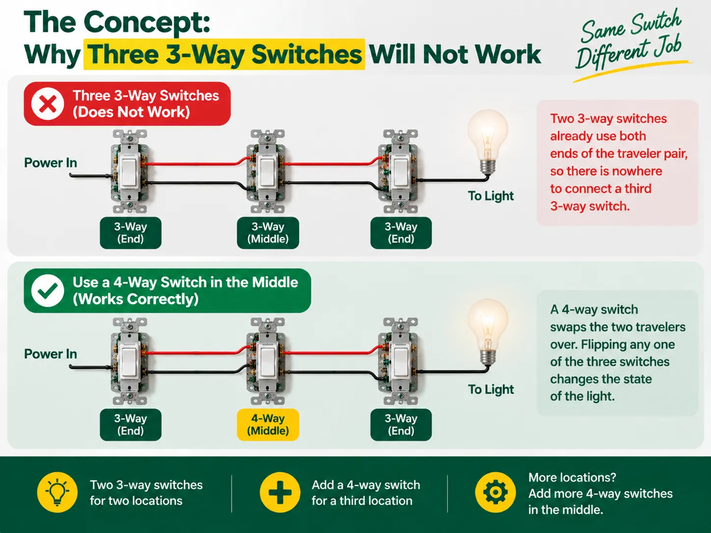
A 3-utas kapcsolókon nincsenek címkék, amelyek jelzik a “be” és “ki” állapotokat, mivel ezek nem kapcsolók a szó szoros értelmében — úgy működnek, mint egy kapcsoló, amely két utazó vezetéket kapcsol össze. Az áramot az első 3-utas kapcsoló küldi az egyik utazón, a másik 3-utas kapcsoló pedig kiválasztja, hogy melyik utazó kapja az áramot, és vezeti a lámpához. Így a két partner a lámpa összekapcsolásának folyamatában egy láncot alkot, ahol a kapcsoló bemeneteknek meg kell egyezniük ahhoz, hogy a lámpa világítson, így a lámpa egyszerűen a kapcsoló megváltoztatásával kikapcsolható.
Azonban, amikor egy harmadik helyszín kerül hozzáadásra, hajlamosak vagyunk észrevenni, hogy a hagyományos 3-utas kapcsolók rendszere már létrehozta a kapcsolatot a traveler kábel mindkét végén, ami megakadályozza egy további kapcsoló csatlakoztatását. Amire szükség van, az egy teljesen más eszköz, amelyet 4-utas kapcsolónak hívnak, és amely két traveler között van elhelyezve, készen arra, hogy kicserélje őket. A 4-utas kapcsolóval minden kapcsoló képes lesz megváltoztatni a fény állapotát, amikor a kapcsolót be- vagy kikapcsolják, így elérve a három helyszínről kívánt eredményt. Ha szükség van a negyedik kapcsoló csatlakoztatására, a helyszínen lévő eszközök száma megnő, de az elv ugyanaz.
Mielőtt elkezdenénk, érdemes megérteni, hogyan illeszkedik össze az egész kapcsolócsalád — a 1-utas (egypólusú), 2-utas (3-utas) és köztes (4-utas) kialakítások közötti különbséget, valamint azt, hogy hogyan vannak címkézve a piacokon, a mi különböző típusú elektromos kapcsolók útmutatójában magyarázzuk..
| Tétel | Specifikáció |
|---|---|
| 3-utas kapcsolók × 2 | Egy a tápellátás végén, egy a fény végén; mindkettő “közös” terminállal és két traveler terminállal |
| 4-utas kapcsoló × 1 | A középső helyszínhez; négy terminál (két pár traveler) |
| Kábel | 14 AWG egy 15 A áramkörön vagy 12 AWG egy 20 A áramkörön (soha ne keverje a méreteket egy áramkörön) |
| Kábel | 14/2 vagy 12/2 (fázis, nulla, föld) plusz 14/3 vagy 12/3 a három doboz között a két traveler plusz nulla számára |
| Dobozt és kábelcsatlakozókat | Megfelelő méretű elosztódobozok, kábelcsavarok vagy karos csatlakozók, szigetelőszalag |
| Szerszámok | Feszültségmérő (érintés nélküli és multiméter), csavarhúzók, kábelcsupaszítók, orrnyeles fogók, zseblámpa |
A legfigyelemreméltóbb fejlesztés a legújabb elektromos kódfrissítésekben az a követelmény, hogy minden kapcsolódobozban legyen egy nulla kábel, hogy a jövőben támogathassák az intelligens eszközöket. Ha lehetséges, használjon háromkábel-eszközöket (amely tartalmazza a piros travertert) és vezessen egy nulla kábelt az összes kapcsolódobozon. Ha a projekt régi kapcsolók cseréjéről szól, nem pedig új kábelezésről, a dobozellenőrzés és a csere diszciplínája a mi kapcsolócsere útmutató minden helyszínen érvényes.
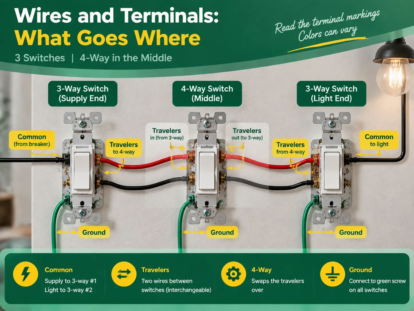
Annak ellenére, hogy a terminálok megnevezése azonos a kiváló minőségű kapcsolók esetében, a színek a gyártótól függően eltérnek, ezért mindig ajánlott ellenőrizni a készülék szövegét. Az egyetemes elfogadott szerep kimondja, hogy:
| Szerep | Kapcsoló | Terminál | Mi kapcsolódik |
|---|---|---|---|
| Közös (fázis) | 3-utas #1 (tápellátás vége) | Sötétebb csavar, vagy jelölve KÖZÖS / C | A forró tápvezeték (a megszakítóból) |
| Travelers | 3-utas #1 | Két megmaradt csavar (sárgaréz, vagy jelölve 1 és 2) | A két traveler kábel, amely a 4-útra fut |
| Traveler pár be | 4-utas (középső) | Egy pár terminál | A 3-utas #1-ből érkező traverterek |
| Traveler pár ki | 4-állású | A másik pár terminál | A traverterek, amelyek a 3-utas #2-hez folytatódnak |
| Travelers | 3-utas #2 (fény vége) | Két traveler csavar | A 4-útról érkező traverterek |
| Common (load) | 3-way #2 | Common terminal | The switched wire running to the light |
The two traveler wires should preferably be colored the same (for example, the black wire and red wire in cable 14/3 for the US or two identical wires in the three-core-and-earth UK cable). In this case, it is good news to know that travelers may be changes without any concerns, provided that they remain unchanged when passing the 4-way switch. However, the common terminal is not interchangeable.
Act with deliberation, one compartment at a time, and treat every wire as hot until you eliminate the doubt.
The verification comes in three steps during which the two common wiring mistakes can be identified – incorrect wiring and crossed traveler continuity.
Almost all unsuccessful three-switch circuits can be attributed to one of the following errors:
Almost none of the aforementioned mistakes can escape being revealed during continuity check; hence “the checking part” is so important.
No, you will never have three 3-way switches in one circuit. You need two 3-way switches to control one light via three power sources, plus one 4-way switch in the middle. To add more than three switches to control the light, you will add another 4-way switch between the 3-way switches.
There are five most practial mistakes: using three 3-way switches instead of two 3-way and one 4-way switch, incorrectly connecting the power source to the traveler terminal instead of the common terminal, switching the neutral instead of connecting it through the wires, incorrectly connecting the travelers in the 4-way switch, and skipping the grounding and labelling of the wires. All these mistakes can be detected by a continuity test before turning the power on.
The 3-way switch has one dark marked terminal (the common terminal) to which the wire from the hot supply at one end and wire from the light at that end of the circuit should be connected. The two brass traveler terminals are to take two wires connecting the 3-way switch with the 4-way one. In the 4-way switch, one pair of traveler wires is to be connected to one pair of terminals.
If these three lights are to be switched on/off simultaneously from all three locations, then the multi-way circuit needs to be made in the same way but the lights have to be connected in parallel from the load-end common terminal. If each of the switches from each location is to control its own light, it is not a multi-way but three independent circuits.
The process of wiring a single light to three switches is an interesting illustration of how understanding the basics leads to effective electrical project completion. In this case, the key concept is the fact that a multiway circuit consists of two 3-way “selector” switches and one or more 4-way “mutator” switches in between. To create a three-way circuit one simply requires two 3-way switches and a 4-way switch wired in a way so that the line feeds the common terminal of the first 3-way switch, travelers run through the 4-way switch, and the common terminal of the last 3-way switch leads to the light. To complete the wiring project correctly, one must do the following: follow the terminal configuration mapping, wire the neutrals straight passing through all boxes, ground components as needed, mark the load and line terminals, and look up for a continuity check on the circuit after its completion. It is also important to remember that only quality switches should be used in the project and that the best switches come from reliable manufacturers. This specific aspect of the process is discussed in detail in the articles on the choice of an electrical switch and socket manufacturer since all the techniques used to check the quality of electrical switches and connectors are the ones used in the manufacturing process of electrical devices.
If you have a long room, hallway, or staircase and want to control one light switch from three different locations which are one at each end of the room and one in the middle. Then you are probably asking one of the most frequently asked and misunderstood questions about home wiring. The answer is surprising: […]

Greenwich kerülete egyedülálló kombinációt kínál a történelmi jelentőség és a modernitás között, amely a történelmi helyszínein, valamint a kortárs lakóépületein is megfigyelhető. Greenwichben a régi és a modern harmóniában létezik egymás mellett. A grúz építészet antik épületeinek jelenléte ellenére is telepíthetők a […]
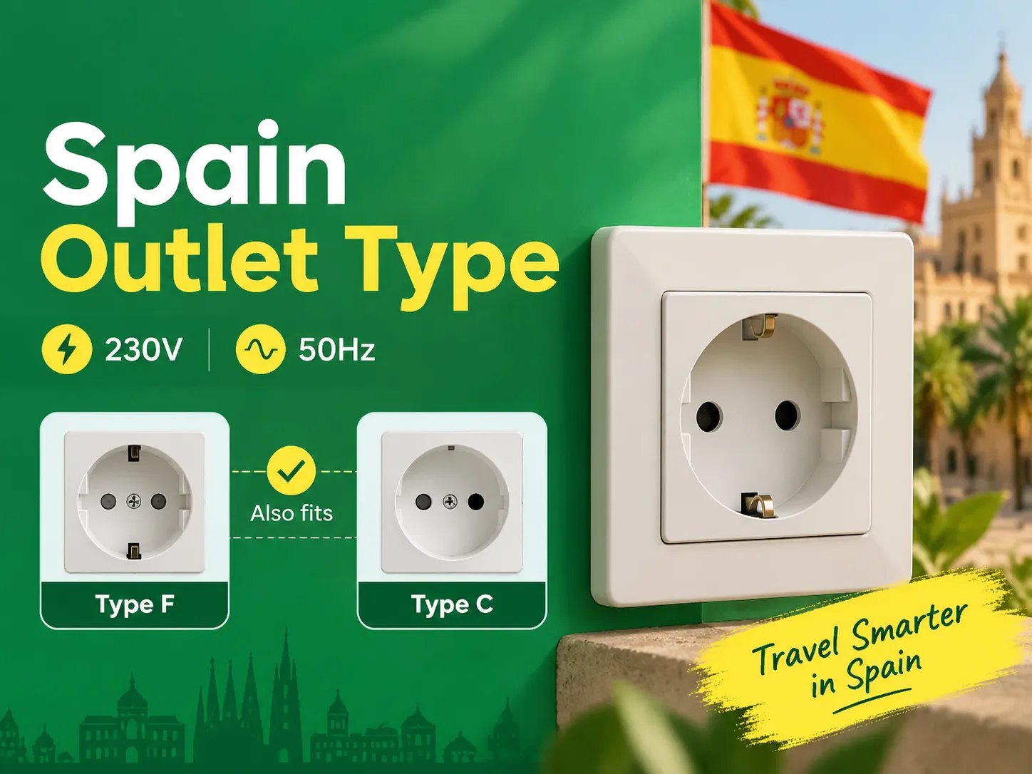
Ha ismeri a két kerek tűs szabályt, akkor észre fogja venni, hogy Spanyolország az egyik legegyszerűbb hely Európában, ahol az eszközeit töltheti és csatlakoztathatja, mivel a szárazföldi országok ugyanazokkal a dugaszoló aljzatokkal rendelkeznek. Azoknak, akik az Egyesült Királyságból, az Egyesült Államokból és Ázsiából utaznak Spanyolországba, csupán egyetlen adapterre van szükségük. Ez a cikk mindent elmagyaráz […]

 No.6 Tuozhan Road, Leshang Pioneer Park, Yueqingwan Bay Harbor, Yueqing város, Zhejiang tartomány


