

Se hai una stanza lunga, un corridoio o una scala e vuoi controllare un interruttore della luce da tre diverse posizioni, che sono una a ciascun estremo della stanza e una nel mezzo. Allora probabilmente stai ponendo una delle domande più frequenti e fraintese riguardo al cablaggio domestico. La risposta è sorprendente: il circuito non è cablato utilizzando tre interruttori a 3 vie. Invece, quando un circuito è controllato da tre posizioni, richiede due interruttori a 3 vie a entrambe le estremità del circuito e un interruttore a 4 vie da collegare utilizzando i due conduttori viaggiatori. Questo articolo discute tutto ciò che riguarda il concetto, gli strumenti, i passaggi coinvolti nel cablaggio, la mappatura dei terminali, il processo di verifica e le specifiche per evitare errori che vengono commessi principalmente da dilettanti.
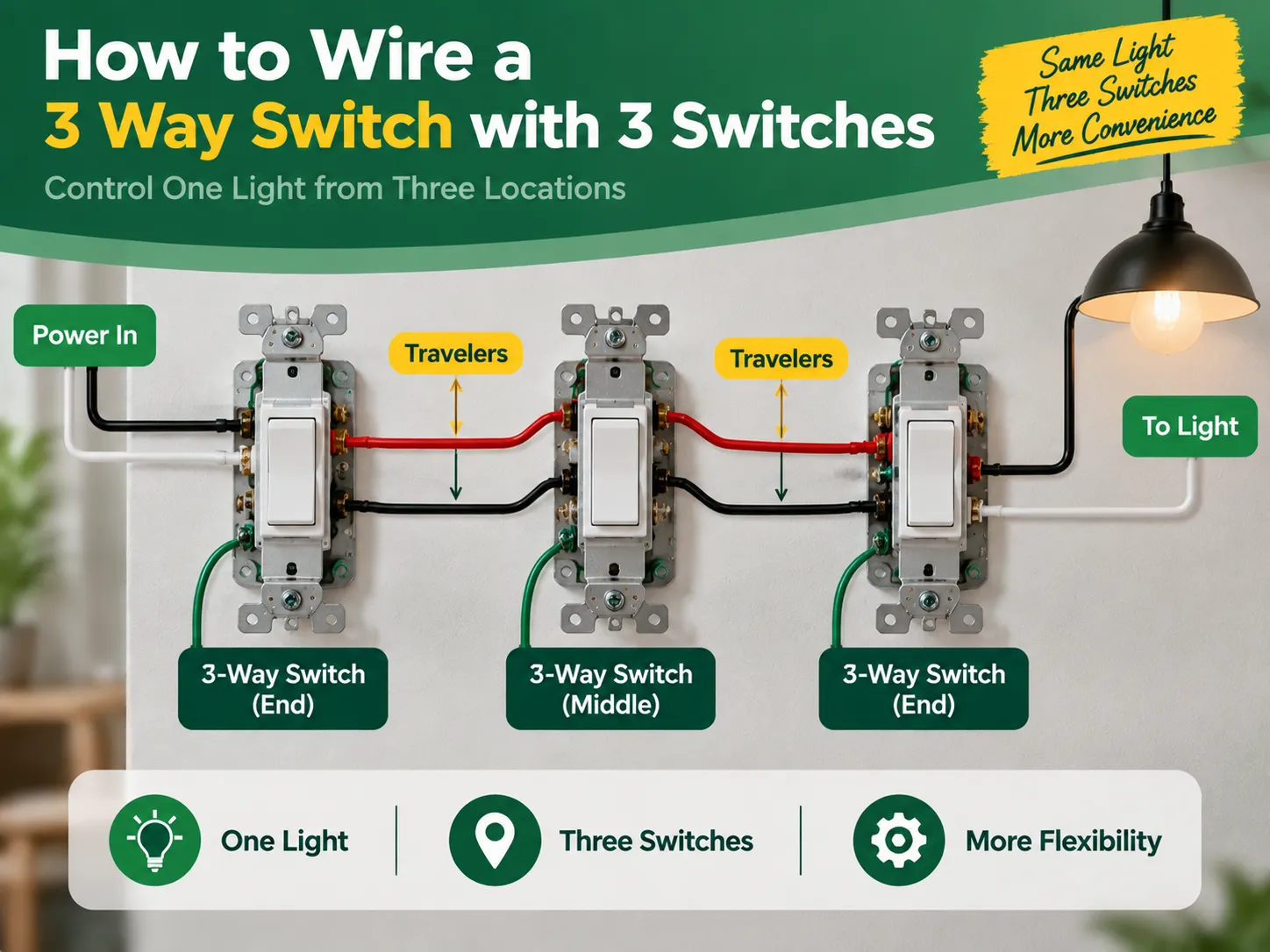
La risposta è breve: per controllare una luce da tre interruttori hai bisogno solo di due interruttori a 3 vie e un interruttore a 4 vie invece di tre interruttori a 3 vie. Il primo interruttore a 3 vie riceve l'alimentazione attraverso il suo terminale comune e invia la corrente attraverso i due fili viaggiatori. L'interruttore a 4 vie è vicino al centro e commuta i viaggiatori ai suoi terminali. L'ultimo interruttore a 3 vie riceve i fili viaggiatori e invia nuovamente l'alimentazione commutata alla luce. Quindi ogni volta che uno degli interruttori dei tre viene attivato, la luce si accende o si spegne indipendentemente dalla posizione degli altri interruttori. Dovresti disattivare l'alimentazione dal quadro elettrico, controllarla con un tester, etichettare correttamente ogni filo e seguire gli schemi forniti di seguito.
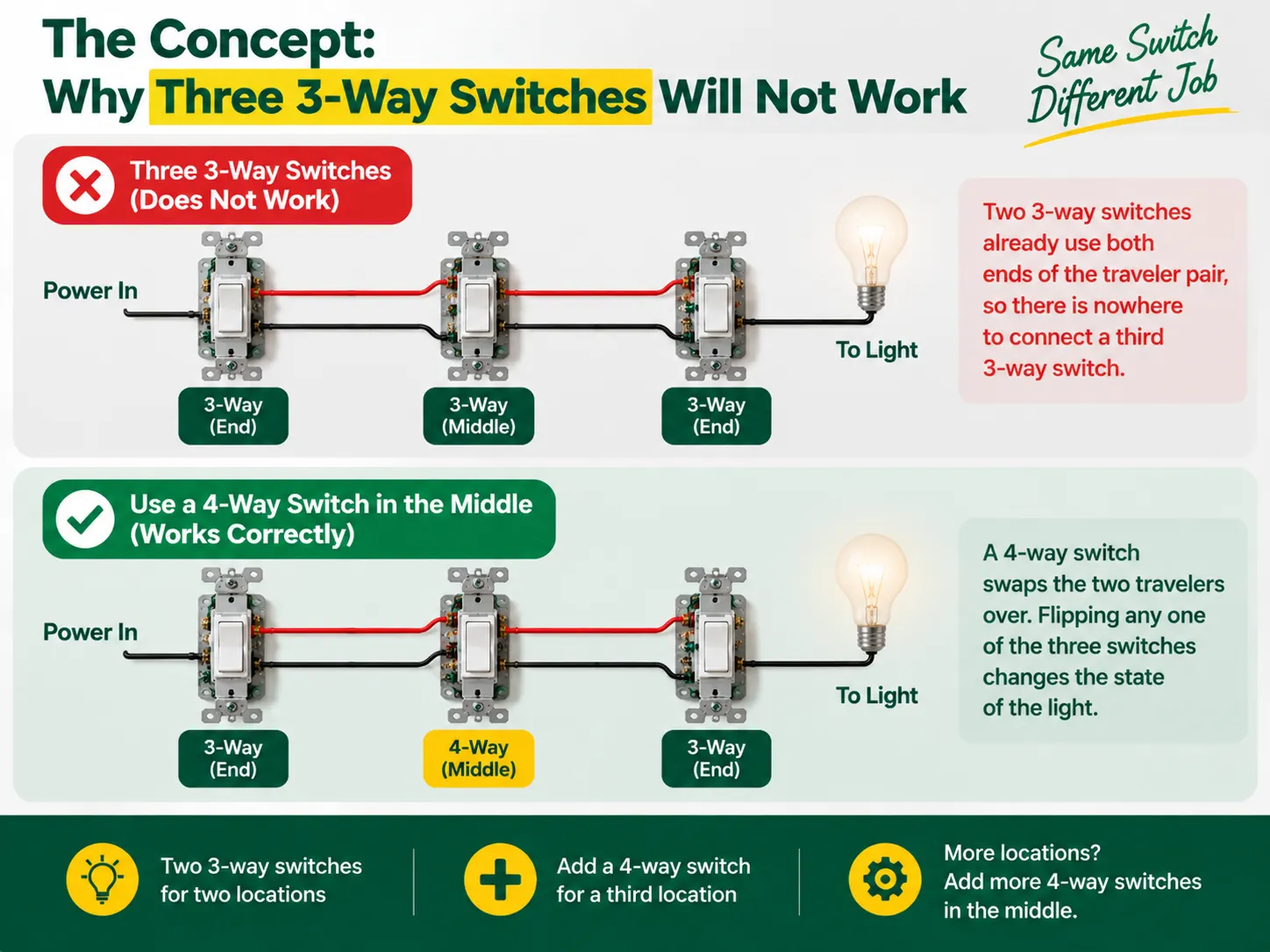
Non ci sono etichette che indicano “on” e “off” negli interruttori a 3 vie poiché non sono interruttori nel vero senso —funzionano come un interruttore che collega due fili viaggiatori. L'alimentazione viene inviata a uno dei viaggiatori dal primo interruttore a 3 vie e l'altro interruttore a 3 vie sceglie quale viaggiatore riceve l'alimentazione e porta alla lampadina. Così i due partner in questo processo di collegamento della lampadina formano una catena, dove gli ingressi dell'interruttore devono corrispondere affinché la lampadina si accenda, quindi la luce si spegne semplicemente cambiando l'interruttore.
Tuttavia, quando viene aggiunta una terza posizione, si tende a vedere che il sistema tradizionale di interruttori 3 vie ha già stabilito una connessione con entrambe le estremità del cavo viaggiatore, il che preclude la connessione di un ulteriore interruttore lì. Ciò che è necessario è un dispositivo totalmente diverso chiamato interruttore 4 vie, che è montato tra due viaggiatori pronti a scambiarli. Con l'interruttore 4 vie in posizione, ogni interruttore sarà in grado di cambiare lo stato della luce ogni volta che l'interruttore viene acceso o spento, raggiungendo così un risultato desiderato da tre posizioni. Se c'è bisogno di collegare il quarto interruttore, il numero dei dispositivi in posizione aumenta ma il principio rimane lo stesso.
Prima di iniziare, vale la pena comprendere come l'intera famiglia di interruttori si adatti insieme — la differenza tra design 1 via (monofase), 2 vie (3 vie) e intermedio (4 vie), e come sono etichettati nei vari mercati, è spiegata nel nostro guida ai diversi tipi di interruttori elettrici.
| Articolo | Specificazione |
|---|---|
| interruttori 3 vie × 2 | Uno per l'estremità di alimentazione, uno per l'estremità della luce; entrambi con un terminale “comune” più due terminali viaggiatori |
| interruttore 4 vie × 1 | Per la posizione centrale; quattro terminali (due coppie di viaggiatori) |
| Filo | 14 AWG su un circuito da 15 A o 12 AWG su un circuito da 20 A (non mescolare mai le dimensioni su un circuito) |
| Cavo | 14/2 o 12/2 (linea, neutro, terra) più 14/3 o 12/3 tra le tre scatole per i due viaggiatori più neutro |
| Scatole e connettori per fili | Scatole di giunzione della dimensione corretta, dadi per fili o connettori a leva, nastro isolante |
| Strumenti | Tester di tensione (senza contatto e multimetro), cacciaviti, spelafili, pinze a becchi, torcia |
Lo sviluppo più significativo nelle recenti aggiornamenti del codice elettrico è un requisito che un cavo neutro sia incluso in ogni scatola di interruttori in modo che i dispositivi smart possano essere supportati in futuro. Se possibile, utilizzare cablaggi a tre cavi (che includono il viaggiatore rosso) e far passare un cavo neutro attraverso tutte le scatole degli interruttori. Se il tuo progetto prevede la sostituzione di vecchi interruttori piuttosto che un nuovo cablaggio, la disciplina di controllo delle scatole e sostituzione nel nostro guida alla sostituzione dell'interruttore della luce si applica in ogni posizione.
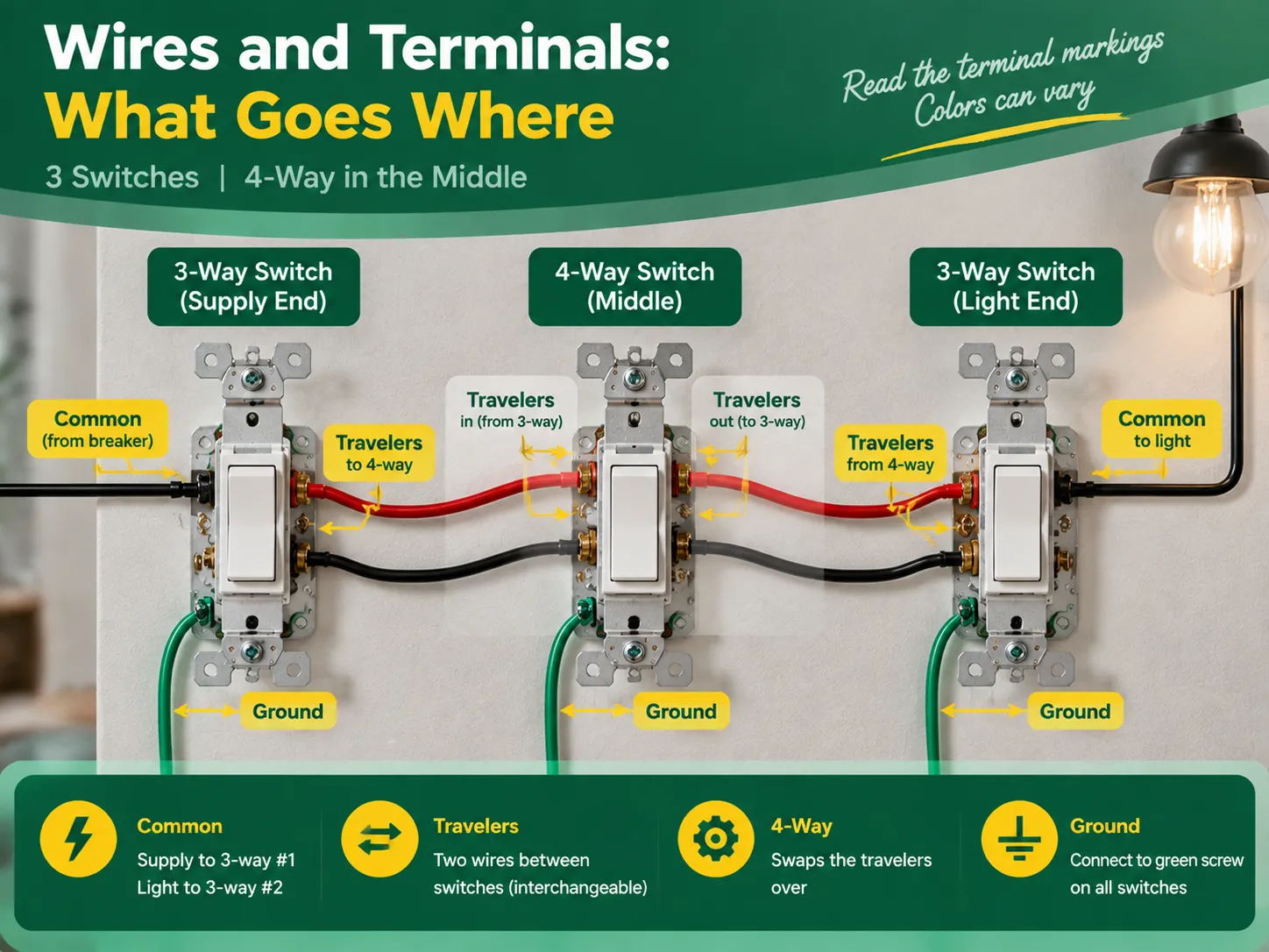
Nonostante il fatto che le designazioni dei terminali siano le stesse per interruttori di alta qualità, i colori differiscono in base al produttore, ed è quindi sempre consigliabile controllare il testo sull'apparecchio. La regola universalmente accettata stabilisce che:
| Regola | Interruttore | Terminale | Ciò che collega |
|---|---|---|---|
| Comune (linea) | 3 vie #1 (estremità di alimentazione) | Vite più scura, o contrassegnata COMUNE / C | Il filo di alimentazione (dal interruttore) |
| Travelers | 3 vie #1 | Le due viti rimanenti (ottone, o contrassegnate 1 e 2) | I due fili viaggiatori che vanno al 4 vie |
| Coppia di viaggiatori in | 4 vie (centrale) | Una coppia di terminali | I viaggiatori provenienti da 3 vie #1 |
| Coppia di viaggiatori out | A 4 vie | L'altra coppia di terminali | I viaggiatori che continuano verso 3 vie #2 |
| Travelers | 3 vie #2 (estremità della luce) | Due viti viaggiatrici | I viaggiatori provenienti dal 4 vie |
| Common (load) | 3-way #2 | Common terminal | The switched wire running to the light |
The two traveler wires should preferably be colored the same (for example, the black wire and red wire in cable 14/3 for the US or two identical wires in the three-core-and-earth UK cable). In this case, it is good news to know that travelers may be changes without any concerns, provided that they remain unchanged when passing the 4-way switch. However, the common terminal is not interchangeable.
Act with deliberation, one compartment at a time, and treat every wire as hot until you eliminate the doubt.
The verification comes in three steps during which the two common wiring mistakes can be identified – incorrect wiring and crossed traveler continuity.
Almost all unsuccessful three-switch circuits can be attributed to one of the following errors:
Almost none of the aforementioned mistakes can escape being revealed during continuity check; hence “the checking part” is so important.
No, you will never have three 3-way switches in one circuit. You need two 3-way switches to control one light via three power sources, plus one 4-way switch in the middle. To add more than three switches to control the light, you will add another 4-way switch between the 3-way switches.
There are five most practial mistakes: using three 3-way switches instead of two 3-way and one 4-way switch, incorrectly connecting the power source to the traveler terminal instead of the common terminal, switching the neutral instead of connecting it through the wires, incorrectly connecting the travelers in the 4-way switch, and skipping the grounding and labelling of the wires. All these mistakes can be detected by a continuity test before turning the power on.
The 3-way switch has one dark marked terminal (the common terminal) to which the wire from the hot supply at one end and wire from the light at that end of the circuit should be connected. The two brass traveler terminals are to take two wires connecting the 3-way switch with the 4-way one. In the 4-way switch, one pair of traveler wires is to be connected to one pair of terminals.
If these three lights are to be switched on/off simultaneously from all three locations, then the multi-way circuit needs to be made in the same way but the lights have to be connected in parallel from the load-end common terminal. If each of the switches from each location is to control its own light, it is not a multi-way but three independent circuits.
The process of wiring a single light to three switches is an interesting illustration of how understanding the basics leads to effective electrical project completion. In this case, the key concept is the fact that a multiway circuit consists of two 3-way “selector” switches and one or more 4-way “mutator” switches in between. To create a three-way circuit one simply requires two 3-way switches and a 4-way switch wired in a way so that the line feeds the common terminal of the first 3-way switch, travelers run through the 4-way switch, and the common terminal of the last 3-way switch leads to the light. To complete the wiring project correctly, one must do the following: follow the terminal configuration mapping, wire the neutrals straight passing through all boxes, ground components as needed, mark the load and line terminals, and look up for a continuity check on the circuit after its completion. It is also important to remember that only quality switches should be used in the project and that the best switches come from reliable manufacturers. This specific aspect of the process is discussed in detail in the articles on the choice of an electrical switch and socket manufacturer since all the techniques used to check the quality of electrical switches and connectors are the ones used in the manufacturing process of electrical devices.
If you have a long room, hallway, or staircase and want to control one light switch from three different locations which are one at each end of the room and one in the middle. Then you are probably asking one of the most frequently asked and misunderstood questions about home wiring. The answer is surprising: […]

Il distretto di Greenwich offre una combinazione unica di importanza storica e modernità, che può essere vista nei suoi siti storici così come nei suoi moderni edifici residenziali. A Greenwich, il vecchio e il moderno coesistono in armonia. Nonostante la presenza degli edifici antichi dell'architettura georgiana, possono essere installati con il […]
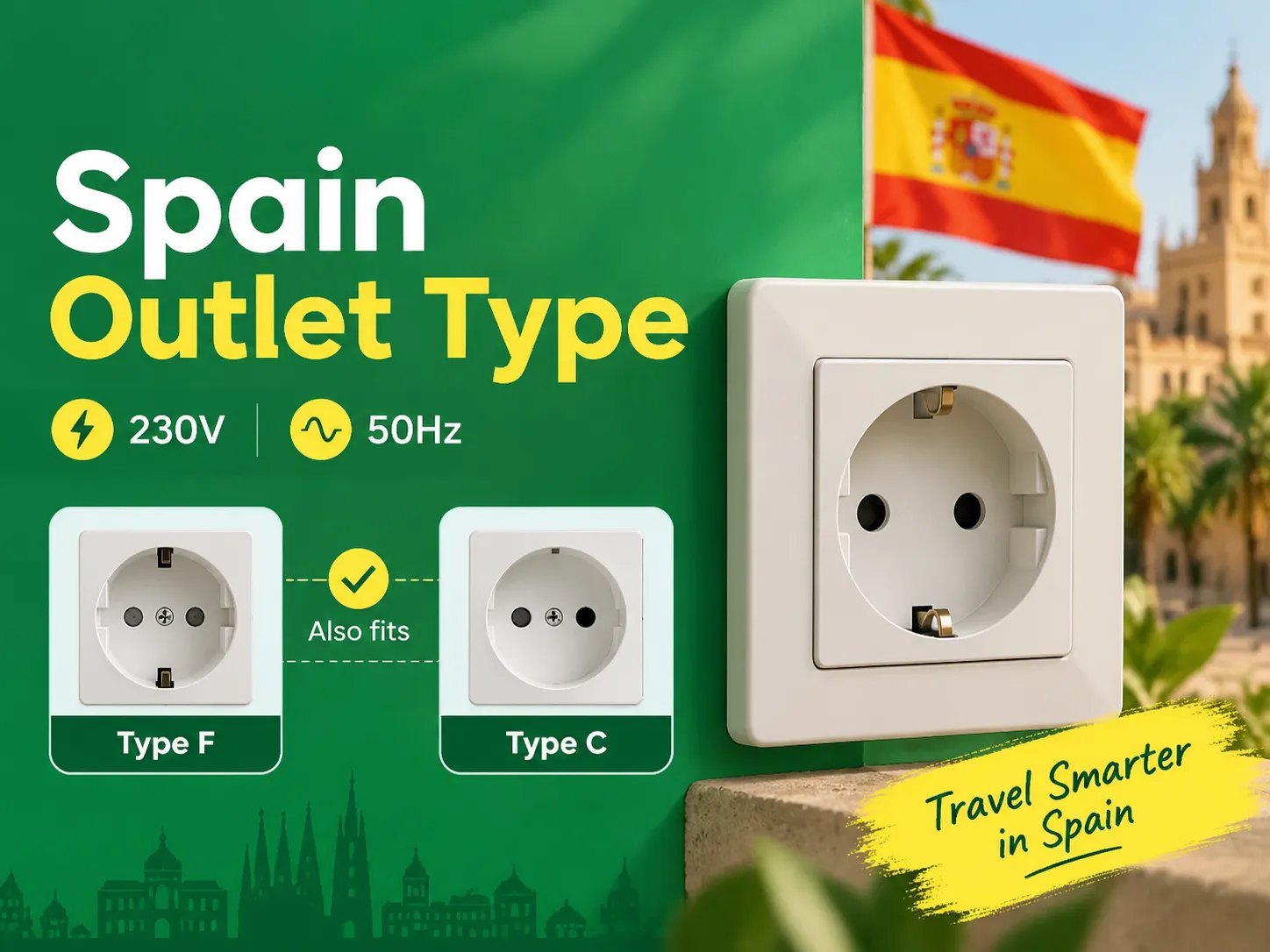
Se conosci le due regole delle spine rotonde, scoprirai che la Spagna è uno dei posti più semplici in Europa per mantenere i tuoi dispositivi caricati e connessi, poiché i paesi del continente hanno le stesse prese. Coloro che viaggiano in Spagna dal Regno Unito, dagli Stati Uniti e dall'Asia necessitano solo di un singolo adattatore. Questo articolo spiega tutto […]

 No.6 Tuozhan Road, Leshang Pioneer Park, porto della baia di Yueqingwan, città di Yueqing, provincia di Zhejiang


