

Tolv-gauge ledning och tjugo-amp kretsar passar så bra ihop att frågorna vanligtvis uppstår från en annan källa. Det kan vara så att installatören har en bit av 12/3 kvar från ett tidigare installationsprojekt eller kanske har leverantören bara 12/3 kablar i lager. Frågan uppstår om huruvida närvaron av en extra ledare har några konsekvenser för hushållsinstallationer. Svaret verkar enkelt men väcker några kodfrågor som påverkar användningen av ledningar, inklusive begränsningarna för små ledare i National Electrical Code, hur tolv-gauge ledning kan bära tjugo ampere innan problem med spänningsfall uppstår, vilka fördelar som kan erbjudas av en extra ledare, och vad som kan hända om en ledare visar sig vara för liten. Följande guide diskuterar alla dessa aspekter samt installationskrav för uttag.
Kort svar: Faktiskt, 12/3 kopparledning är lämplig för en 20 A uttagskrets och motsvarar den minimi ledningsstorlek som krävs i National Electrical Code (NEC) som nämns i Artikel 240.4(D). “3” indikerar att kabeln har tre isolerade ledningar, dvs. svart, röd och vit, plus en bar utrustningsjordledare. Således behöver du bara en svart och en vit ledning i en vanlig 20 A krets, där den röda lämnas oanvänd eller används i en grenkrets. En 12/3 ledning förväntas vara 15-30% dyrare än 12/2, och den andra ledningen påverkar boxfyllnadsberäkningar. När det gäller spänningsfall fungerar 12 AWG bra vid 20 A upp till cirka 40-50 fot. Efter ungefär 75 fot kommer spänningsfallet att överstiga 3% som specificeras av NEC för kretsar, och 10 AWG bör användas.
Metoden för att namnge elektriska kablar är enkel eftersom den bara tar två siffror, som båda är betydelsefulla.
Den första siffran indikerar ledarens gauge med hjälp av American Wire Gauge System. Till exempel; en ledarstorlek av 12 AWG är en 2,05 mm bred kopparledning. Den andra siffran anger hur många ledare det finns i ledningen. I exemplet med ledarnamn 12/3 betyder det att det finns tre isolerade ledare totalt. I fallet med 12/3 NM-B kabel är de tre ledarna svarta, röda och vita isolerade. Det finns också den fjärde ledningen som är den bara ledningen.
Således är 12/3 inte en unik produkt; snarare representerar den en enkel tolv gauge tråd. Därför är trådtypen av 12/2 i sin betydelse och egenskaper. I Amerika bestämmer färgerna på trådarna deras roll; svarta och röda trådar är trådarna under elektrisk tryck, den vita tråden är tråden som inte passerar någon ström, medan den bara används för att koppla alla enheter till en nödvändig krets. De konventioner som gäller för de enheter som dessa ledare matar täcks i vår översikt över de olika typerna av strömbrytare som används i elektriska installationer, och samma logik gäller för uttagskoppling.
I situationen att skapa kretsen för en standard 20 A elektrisk enhet måste det finnas en het tråd, en neutral tråd och den bara effektiva jorden. Därför kan en 12/2 tråd användas och den fjärde behövs överhuvudtaget inte; dock uppstår frågan om den överskottsledaren kan påverka kabelns funktion.

Riktlinjerna är kortfattade och tydliga.
Överströmbegränsningar för små ledare. Artikel 240.4(D) i National Electric Code (NEC) sätter en gräns för överströmsskydd för små ledare, vilket begränsar användningen av 14 AWG till 15 ampere, 12 AWG till 20 ampere och 10 AWG till 30 ampere. Således, på grund av den begränsade förmågan att eliminera värme under sina operationer, blir 12 AWG den rekommenderade tråden för 20 A-krets medan 14 AWG inte kan uppfylla denna roll, även om den praktiskt sett kan göra det.
Ampacitet. När man överväger ampacitet är det avgörande att ta hänsyn till typen av ledare samt temperaturklassningen av isoleringen och installationsförhållandena. När det gäller 12 AWG koppar kan man lita på värdet av 20 A som anges i samband med 60°C och värdet av 25 A som är kopplat till 75°C. NM-B kabel betraktas oftast med hänvisning till 60°C klassningen, vilket innebär att 20 A är exakt det värde man behöver, utan något extra säkerhetsmarginal. Men om omgivningstemperaturen är för hög eller ledarna är bundna tillsammans, kommer nedgradering att börja påverka den praktiska ampaciteten.
Ledare som inte används. Ingenting förbjuder användningen av oanvända ledare. Det enda kravet är att sådana ledare ska avslutas på ett säkert sätt, för att undvika kortslutningar.
Boxfyllning. När det gäller boxfyllning är detta där behovet av extra ledare faktiskt kan medföra vissa kostnader. Enligt Artikel 314.16 i National Electric Code (NEC) måste summan av alla ledare beaktas. När man inför en isolerad fjärde ledare i en kabeldragning, måste det kontrolleras att boxen skulle rymma den.
En ledare som inte används kan utnyttjas på ett bra sätt om den planeras noggrant, som förklaras här nedan.
| Alternativ | Hur det fungerar | Krav och försiktighetsåtgärder |
|---|---|---|
| Avsluta den och lämna den | Avsluta den röda ledaren med en kontakt i båda ändar och märk den som oanvänd | Helt i överensstämmelse; räkna den för boxfyllning; lämna den tillräckligt lång för att identifiera senare |
| Flerledars grenkrets | Svart och röd levererar två separata kretsar som delar den enda vita neutrala | Kräver de två oisolerade ledarna på motsatta faser och samtidig frånkoppling av alla ledare vid panelen, vanligtvis med en tvåpolig brytare eller en godkänd handtagskoppling; GFCI- och AFCI-arrangemang behöver noggrannhet |
| Två uttag, en kabel | Mata det första uttaget på svart, koppla vidare till en andra position på röd, eller dela ett duplexuttag | Tillåtet där lådan och enhetsbetyget tillåter; ett delat duplex kräver en brytbar flik och, i vissa konfigurationer, en tvåpolig brytare |
| Trevägs- eller flerplatsbrytning | Använd svart och röd som resande ledare mellan brytarna | En legitim användning av 12/3, även om kretsen är en belysningskrets snarare än en uttagskrets |
| 240 V-krets | Svart och röd som de två oisolerade ledarna, jord för säkerhet, vit kapslad | Kan inte betjäna ett standard 120 V-uttag; behöver en 240 V-enhet eller en 240 V-belastning |
Låt oss titta noga på den flerledarkretsen eftersom det är anledningen till köpet av 12/3-kabeln. Det är ett mycket typiskt misstag som görs, därför är det värt noggrant övervägande. När två kretsar delar samma neutrala ledare, jämnar strömmen genom den ledaren ut de två kretsarna istället för att addera dem, vilket endast fungerar när ledarna är från två olika faser. Det är viktigt att få detta rätt eftersom annars måste den neutrala ledaren bära den totala strömmen från båda kretsarna, därför kräver lagen att i sådana fall ska kretsen kopplas bort från strömförsörjningen omedelbart, och användning av en tvåpolig brytare är den vanliga metoden i sådana fall. Om den flerledarkretsen förser utrustning som bör förlita sig på GFCI-brytare, blir det mycket mer komplext och faktiskt väljer många elektriker att inte använda den typen av krets i kök och badrum.
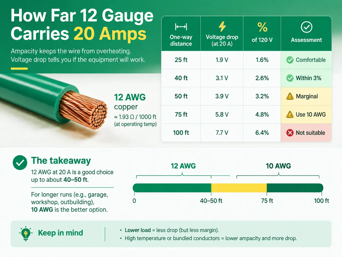
Ampacitet indikerar om kabeln kommer att överhettas, medan spänningsfall avgör om utrustningen i den andra änden fungerar korrekt.
Enligt NEC får spänningsfallet i en grenkrets inte överstiga 3%, medan det totala spänningsfallet från servicepunkten till användningspunkten inte får överstiga 5%. NEC tillåter därför viss avvikelse från dessa värden i bostadsstandarden, men de finns fortfarande.
Anledningen till ovanstående värden är att utrustning beter sig dåligt på grund av låga spänningar. Vid låga spänningar blir motorer varma, elektronik återställs, och resistiva laster fungerar inte som förväntat.
The twelfth gauge copper wire has a resistance of about 1.93 ohms per 1,000 feet at the operating temperature. In 120 volts circuit, the total voltage drop when carrying 20 amps is calculated as presented below.
| One-way distance | Approximate voltage drop at 20 A | Percentage of 120 V | Assessment |
|---|---|---|---|
| 25 ft | 1.9 V | 1.6% | Comfortable |
| 40 ft | 3.1 V | 2.6% | Within the 3% recommendation |
| 50 ft | 3.9 V | 3.2% | Marginally over the recommendation |
| 75 ft | 5.8 V | 4.8% | Too much; step up to 10 AWG |
| 100 ft | 7.7 V | 6.4% | Clearly unsuitable |
On a practical note, 12 AWG cables can handle up to approximately 40-50 feet and 10 AWG is suitable for lengths of about 75 feet or above. Since residential circuits have many receptacles that fall within this distance, the combination is considered standard. Distances in cases of circuits connected to the detached garage or some other outbuilding have to be calculated.
There are two factors involved in the decline in number. The first is that in a circuit that rarely draws the full 20 amps, there is less drop. However, designing on this assumption does not give you any margin for any errors. The other factor involves derating the conductors and the drop that is caused due to the wire’s background temperature or if the envelope has too many wires inside.
Failing in a known way, undersized conductors in a 20 A circuit help bring about the code’s strict insistence on 14 AWG wire.
The popular mistake is to install a bigger fuse to avoid nuisance tripping. However, it can be dangerous because in case of using 12 SWG wire with 20 A circuit connected to a circuit with 30 A fuse, wire will be able to heat up, and it will happen without activating the circuit breaker.
| Kabel | Use it for a 20 A receptacle circuit? | When to choose it |
|---|---|---|
| 14/2 | Inga | 15 A circuits only; prohibited on a 20 A circuit by NEC 240.4(D) |
| 12/2 | Yes — the standard choice | Ordinary 20 A receptacle circuits; cheaper, easier to pull, less box fill |
| 12/3 | Ja | When you need a second ungrounded conductor: multiwire branch circuits, 240 V loads, or traveller conductors |
| 10/2 | Yes — oversized | Long runs where voltage drop exceeds 3%, or high-temperature derating |
| 10/3 | Yes — oversized | 240 V circuits at long distance, or 30 A circuits |
A basic 20 A receptacle circuit likely calls for a 12/2 wire size. While you could use 12/3, this is actually unnecessary since normally there is no use made of the third conductor. If you have some 12/3 leftover, using it does not increase costs in principle apart from some additional box fill and some extra labor to run it through the framing.
When it comes to working with 12 AWG wire, note that the wire is generally stiffer than 14 AWG, as well as it bends more stiffly, leading to the complication of the installation.
The sequence below assumes a conventional daisy-chained receptacle circuit with the cable used in 12/2 fashion. Safe isolation and verification come before anything else, and the general technique — including how to identify conductors when colours are unconventional — is covered in our guide to replacing a light switch, which follows the same discipline.
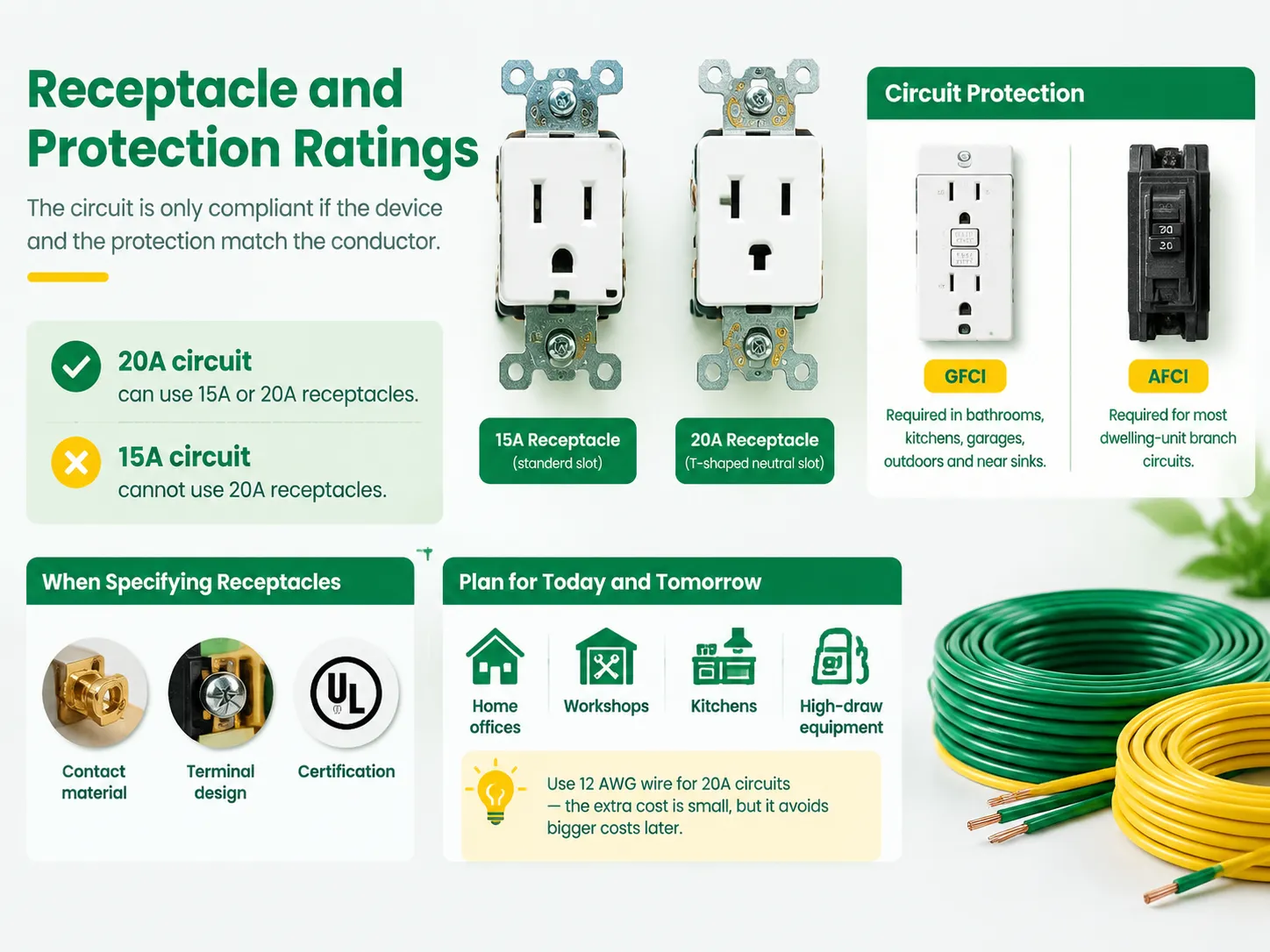
The circuit is only compliant if the gadget and the protection coincide with the conductor.
Receptacle Capacity. A 20 A circuit may have a 15 A receptacle in use. This may surprise some people, but 15 A receptacle is fit for transferring 20 A through to devices relying on it, hence, making it admissible for a 20 A circuit. Conversely, a 20 A receptacle should not be mounted on a 15 A circuit as the latter is not able to provide the power of the device. As to the majority of households, the difference will be seen in face style, which is the way the receptacle looks and in a certain quality of the device, which is better in most cases.
Where receptacles are being specified for a project rather than replaced one at a time, the selection criteria extend to contact material, terminal design, and certification — the same discipline set out in our guide to choosing an electric switch and socket manufacturer.
Capacity is the other half of that decision. Modern receptacle circuits increasingly support more than lamps and vacuum cleaners, and the load profile of the devices plugged into them is changing, as discussed in our article on USB-vägguttag och snabbladdning. Planning the circuit for that reality costs nothing at the wiring stage and a great deal later.
A representative example of how a modern device in this family is documented is our FS328-V dimmer specification, which is the level of detail a specifier should expect before committing a circuit to a device.
One final note for people who install a 20 A circuit: 20 A circuits are being used more often for home offices, workshops, kitchens, or any other location that has a lot of powerful appliances. The cost of using 14 AWG or 12 AWG wire is not much different when considering the cost of opening up a wall later, therefore it might be best to use twelve gauge.
Absolutely. Twelve-gauge copper is a universal wire for any typical 20 A circuit due to it (Secretary Committee (erroneous text: “due to its”), National Electric Code or NEC) being the lowest size acceptable by NEC under the rules for small conductors provided in Article 240.4(D). Standard wire assembly for a 20 A company is a 20 A receptacle using 12 AWG wire and protected with a 20 A breaker. The only requirement is the circuit protection shall follow the convention and must be calibrated at 20 A. This means one cannot install 12 AWG wire and substitute a 30 A breaker for a standard company operation since such actions would disable the protection provided to the wire.
In practice, twelve-gauge copper is the generally accepted wiring solution as well. An alternative solution for 20 A circuits would be ten gauge wire; however, this is only necessary for runs of wire longer than 75 feet where the voltage drop is nonnegligible, or if wire is exposed to high temperature or tightly bundled with other conductors. Fourteen-gauge wire cannot be used in 20 A circuits since according to Article 240.4(D) fourteen AWG wire only limits the performance at 15 A.
When it comes to 20 A current conduction capacity (ampacity), the answer is yes – conducted current is mainly limited by voltage drop rather than the distance. With regard to 20 A of conducted current, 12 AWG copper wires have nearly 3.9 V drop at 50 ft run length and nearly 5.8 V drop at 75 ft run. Therefore, the voltage drop ratio at 20 A of current conduction is approximately 3.2% and 4.8% respectively which allows for the distance of up to 40-50 ft for a 20 A current conduction along 12 AWG wire without any significant voltage drop. In case of longer wire runs it would be better to use ten AWG wire.
Yes, it is possible to install 12/3 wire to a socket as it does not contradict any regulations. One need only close the red wire to both ends in order to utilize it exactly the same way as it is done for 12/2 wires. Another alternative could be a multiwire circuit installation powered by 12/3 cable.
The installation will be highly unsafe, as well as not compliant with any wiring regulations. The thing is that under normal conditions nobody can use fourteen gauge wire for conduction of more than 15 A since Article 240.4(D) of the (wrong phrase: “the”) National Electric Code says that fourteen AWG wire is limited to 15 A. This is why current load will overheat the wire making it unfit for the installation.
For a circuit with a receptacle of 20 A that is made with twelve-three wire, it is permissible as well as reasonable and does not compromise whatsoever. Twelve AWG is the least that the code allows for a 20 A outlet and the extra insulated wire may or may not be used, and compliant capping can be done in two minutes. The important part of making the circuit safe is everything that surrounds the cable: a 20 A circuit being protected with a 20 A circuit breaker, wall socket that corresponds to output rating, GFCI or AFCI protection that is mandated by location, correctly torqued terminations, and run that is short enough for impedance to stay below three percent. If all the above is above board, then the question of whether to use 12/2 or 12/3 depends on convenience and cost rather than compliance.
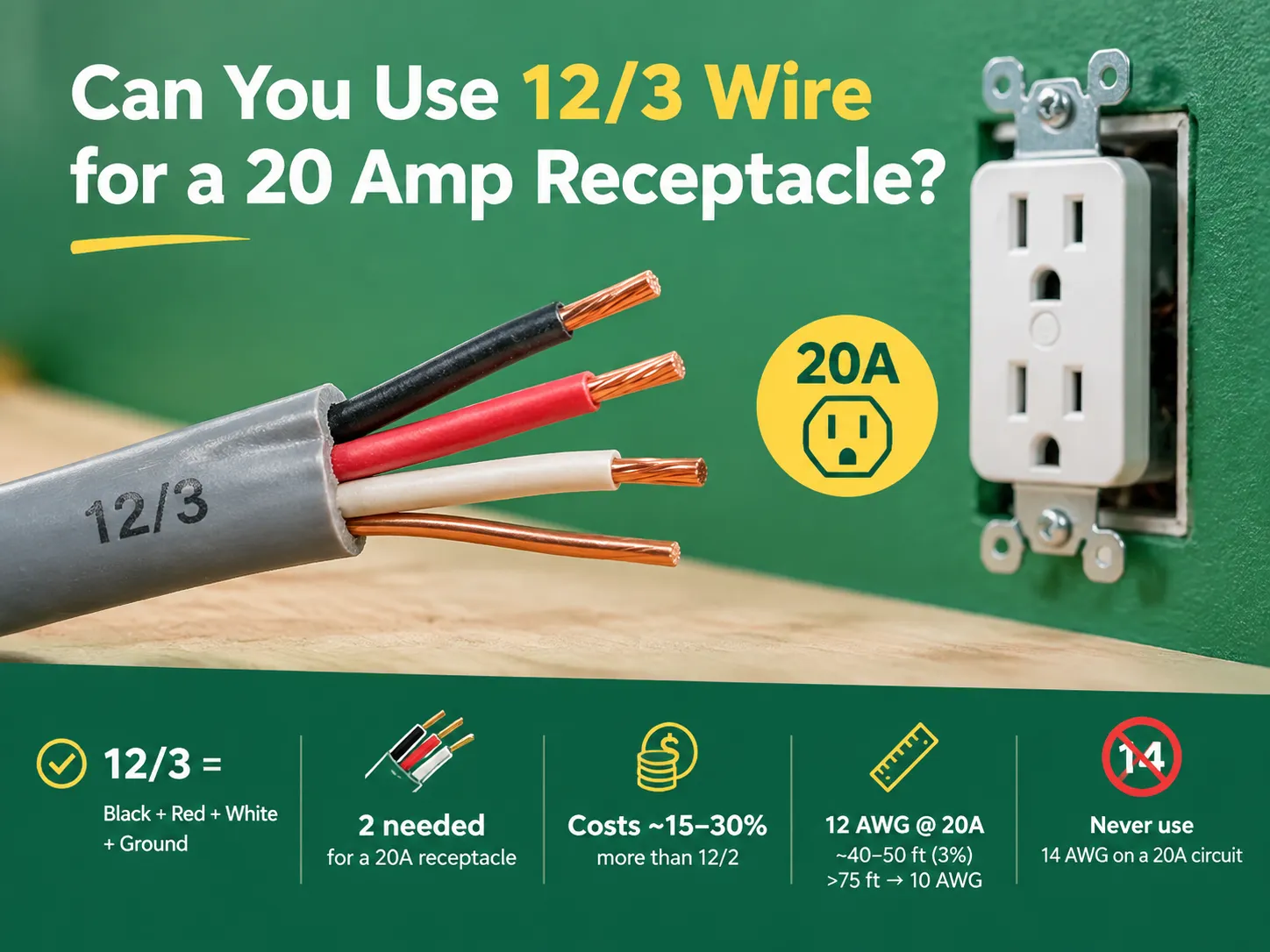
Twelve-gauge wire and twenty-amp circuits go together so well that the questions generally arise from a different source. It may be the case that the installer has a piece of 12/3 left over from an earlier wiring project or perhaps the supplier only has 12/3 cables in stock. The question comes up as to whether […]

Den exceptionella situationen i Dubais elektriska apparatssektor, som kombinerar brittiska standardapparater med regler från ett verk samt en nationell myndighet som övervakar genomförandet av nationella regler, kräver att apparaterna ska kunna tåla de höga temperaturerna och den fuktighet som upplevs i regionen på grund av dess kustläge, och också […]

“Hur många uttag är tillåtna på en 20 amp krets?” är en av de mest populära frågorna som folk skulle ställa när det gäller att utföra elektriskt arbete hemma. Tyvärr är det också en av de frågor som har besvarats mest felaktigt; de flesta människor skulle ge ett nummer baserat på personlig åsikt snarare […]

 No.6 Tuozhan Road, Leshang Pioneer Park, Yueqingwan Bay Harbor, Yueqing stad, Zhejiang-provinsen


