

Als je een lange kamer, gang of trap hebt en één lichtschakelaar vanuit drie verschillende locaties wilt bedienen, die zich aan elk uiteinde van de kamer en één in het midden bevinden. Dan stel je waarschijnlijk een van de meest gestelde en verkeerd begrepen vragen over huisbedrading. Het antwoord is verrassend: de schakeling is niet bedraad met drie 3-weg schakelaars. In plaats daarvan, wanneer een schakeling vanuit drie locaties wordt bediend, zijn er twee 3-weg schakelaars aan beide uiteinden van de schakeling en één vier-weg schakelaar nodig die met de twee reizigersdraden is verbonden. Dit artikel bespreekt alles wat met het concept, gereedschappen, stappen bij het bedraden, aansluitingen, verificatieproces en specificaties te maken heeft om fouten te vermijden die meestal door amateurs worden gemaakt.
Het antwoord is kort: Om één licht vanuit drie schakelaars te bedienen, heb je slechts twee 3-weg schakelaars en één vier-weg schakelaar nodig in plaats van drie 3-weg schakelaars. De eerste 3-weg schakelaar ontvangt de stroomvoorziening via zijn gemeenschappelijke aansluiting en stuurt de stroom via de twee reizigersdraden. De vier-weg schakelaar bevindt zich nabij het midden en schakelt de reizigers bij zijn aansluitingen. De laatste 3-weg schakelaar ontvangt de reizigersdraden en stuurt opnieuw de geschakelde stroom naar het licht. Dus wanneer een van de drie schakelaars wordt ingeschakeld, wordt het licht aan of uit gezet, ongeacht de positie van de andere schakelaars. Je moet de stroom uitschakelen vanaf de elektrische zekering, het controleren met een tester, elke draad goed labelen en de schema's hieronder volgen.
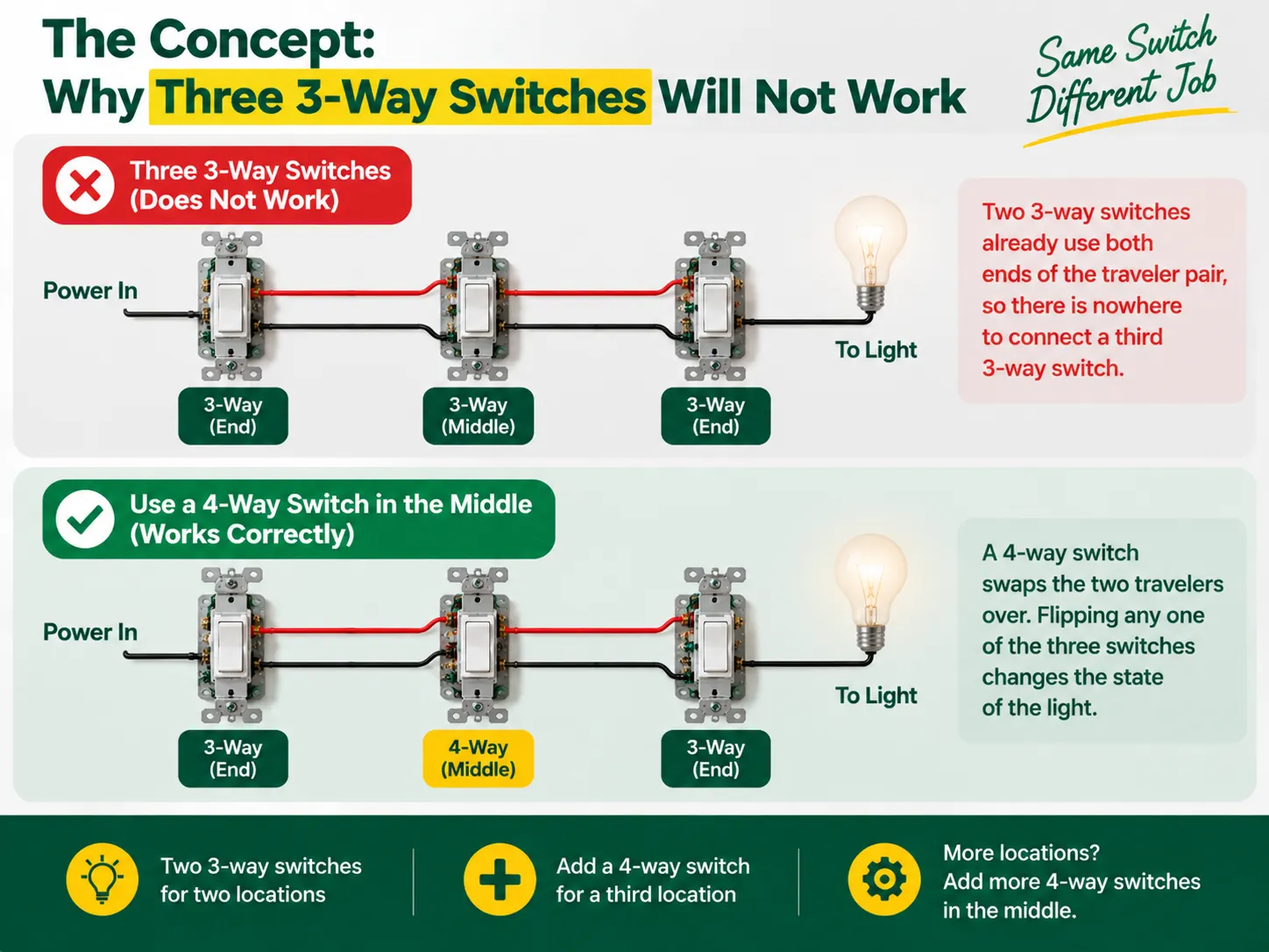
Er zijn geen labels die “aan” en “uit” aangeven in 3-weg schakelaars, aangezien ze geen schakelaars in de ware zin zijn — ze functioneren als een schakelaar die twee reizigersdraden verbindt. De stroom wordt naar een van de reizigers gestuurd door de eerste 3-weg schakelaar en de andere 3-weg schakelaar kiest welke reiziger de stroom ontvangt en naar de lamp leidt. Zo vormen de twee partners in dit proces van het verbinden van de lamp een keten, waarbij de ingangen van de schakelaar moeten overeenkomen om de lamp te laten branden, zodat het licht simpelweg uitgaat door de schakelaar te veranderen.
Echter, wanneer een derde locatie wordt toegevoegd, ziet men vaak dat het traditionele systeem van 3-weg schakelaars al verbinding heeft gemaakt met beide uiteinden van de reiziger kabel, wat het aansluiten van een extra schakelaar daar uitsluit. Wat nodig is, is een totaal ander apparaat genaamd een 4-weg schakelaar, die tussen twee reizigers wordt gemonteerd om ze te verwisselen. Met de 4-weg schakelaar op zijn plaats, kan elke schakelaar de status van het licht veranderen elke keer dat de schakelaar aan of uit wordt gezet, waardoor het gewenste resultaat vanuit drie locaties wordt bereikt. Als er behoefte is aan de aansluiting van de vierde schakelaar, wordt het aantal apparaten verhoogd, maar het principe blijft hetzelfde.
Voordat u begint, is het de moeite waard om te begrijpen hoe de hele schakelaarfamilie in elkaar past — het verschil tussen 1-weg (enkelpolig), 2-weg (3-weg) en tussenliggende (4-weg) ontwerpen, en hoe ze op de markten worden gelabeld, wordt uitgelegd in onze gids voor de verschillende soorten elektrische schakelaars.
| Artikel | Specificatie |
|---|---|
| 3-weg schakelaars × 2 | Eén voor het voedingsuiteinde, één voor het lichtuiteinde; beide met een “gemeenschappelijke” terminal plus twee reiziger terminals |
| 4-weg schakelaar × 1 | Voor de middelste locatie; vier terminals (twee paren van reizigers) |
| Draad | 14 AWG op een 15 A circuit of 12 AWG op een 20 A circuit (mix nooit maten op één circuit) |
| Kabel | 14/2 of 12/2 (lijn, neutraal, aarde) plus 14/3 of 12/3 tussen de drie dozen voor de twee reizigers plus neutraal |
| Dozen en draadverbindingen | Juiste maat junction dozen, draadmoeren of leversverbindingen, elektrische tape |
| Gereedschap | Spanningstester (non-contact en multimeter), schroevendraaiers, draadstripper, punttang, zaklamp |
De meest opmerkelijke ontwikkeling in recente updates van de elektrische code is een vereiste dat een neutrale kabel in elke schakeldoos moet worden opgenomen, zodat slimme apparaten in de toekomst kunnen worden ondersteund. Indien mogelijk, gebruik driekabelbedrading (die de rode reiziger omvat) en loop een neutrale kabel door alle schakeldozen. Als uw project oude schakelaars vervangt in plaats van nieuwe bedrading, geldt de dooscontrole en vervangingsdiscipline in onze lichtschakelaar vervangingsgids toepast op elke locatie.
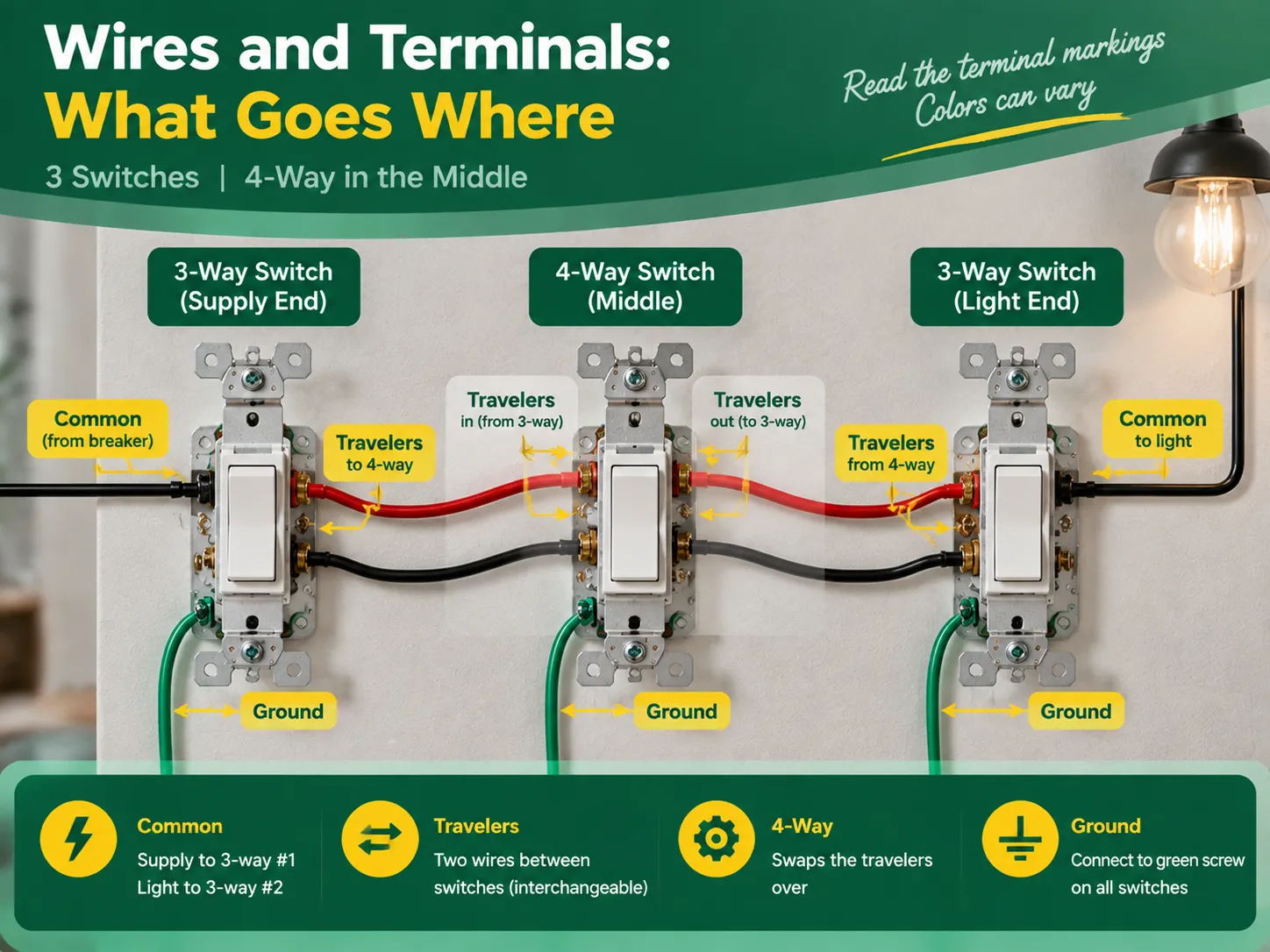
Ondanks het feit dat de terminalaanduidingen hetzelfde zijn voor hoogwaardige schakelaars, verschillen de kleuren op basis van de fabrikant, en het is daarom altijd raadzaam om de tekst op het apparaat te controleren. De universeel aanvaarde rol stelt dat:
| Rol | Schakelaar | Terminal | Wat verbindt |
|---|---|---|---|
| Gemeenschappelijk (lijn) | 3-weg #1 (voedingsuiteinde) | Donkere schroef, of gemarkeerd GEMEENSCHAP / C | De hete voedingsdraad (van de schakelaar) |
| Travelers | 3-weg #1 | Twee resterende schroeven (messing, of gemarkeerd 1 en 2) | De twee reiziger draden die naar de 4-weg gaan |
| Reiziger paar in | 4-weg (midden) | Eén paar terminals | De reizigers die komen van 3-weg #1 |
| Reiziger paar uit | Hotelschakelaar | Het andere paar terminals | De reizigers die doorgaan naar 3-weg #2 |
| Travelers | 3-weg #2 (lichtuiteinde) | Twee reiziger schroeven | De reizigers die komen van de 4-weg |
| Common (load) | 3-way #2 | Common terminal | The switched wire running to the light |
The two traveler wires should preferably be colored the same (for example, the black wire and red wire in cable 14/3 for the US or two identical wires in the three-core-and-earth UK cable). In this case, it is good news to know that travelers may be changes without any concerns, provided that they remain unchanged when passing the 4-way switch. However, the common terminal is not interchangeable.
Act with deliberation, one compartment at a time, and treat every wire as hot until you eliminate the doubt.
The verification comes in three steps during which the two common wiring mistakes can be identified – incorrect wiring and crossed traveler continuity.
Almost all unsuccessful three-switch circuits can be attributed to one of the following errors:
Almost none of the aforementioned mistakes can escape being revealed during continuity check; hence “the checking part” is so important.
No, you will never have three 3-way switches in one circuit. You need two 3-way switches to control one light via three power sources, plus one 4-way switch in the middle. To add more than three switches to control the light, you will add another 4-way switch between the 3-way switches.
There are five most practial mistakes: using three 3-way switches instead of two 3-way and one 4-way switch, incorrectly connecting the power source to the traveler terminal instead of the common terminal, switching the neutral instead of connecting it through the wires, incorrectly connecting the travelers in the 4-way switch, and skipping the grounding and labelling of the wires. All these mistakes can be detected by a continuity test before turning the power on.
The 3-way switch has one dark marked terminal (the common terminal) to which the wire from the hot supply at one end and wire from the light at that end of the circuit should be connected. The two brass traveler terminals are to take two wires connecting the 3-way switch with the 4-way one. In the 4-way switch, one pair of traveler wires is to be connected to one pair of terminals.
If these three lights are to be switched on/off simultaneously from all three locations, then the multi-way circuit needs to be made in the same way but the lights have to be connected in parallel from the load-end common terminal. If each of the switches from each location is to control its own light, it is not a multi-way but three independent circuits.
The process of wiring a single light to three switches is an interesting illustration of how understanding the basics leads to effective electrical project completion. In this case, the key concept is the fact that a multiway circuit consists of two 3-way “selector” switches and one or more 4-way “mutator” switches in between. To create a three-way circuit one simply requires two 3-way switches and a 4-way switch wired in a way so that the line feeds the common terminal of the first 3-way switch, travelers run through the 4-way switch, and the common terminal of the last 3-way switch leads to the light. To complete the wiring project correctly, one must do the following: follow the terminal configuration mapping, wire the neutrals straight passing through all boxes, ground components as needed, mark the load and line terminals, and look up for a continuity check on the circuit after its completion. It is also important to remember that only quality switches should be used in the project and that the best switches come from reliable manufacturers. This specific aspect of the process is discussed in detail in the articles on the choice of an electrical switch and socket manufacturer since all the techniques used to check the quality of electrical switches and connectors are the ones used in the manufacturing process of electrical devices.
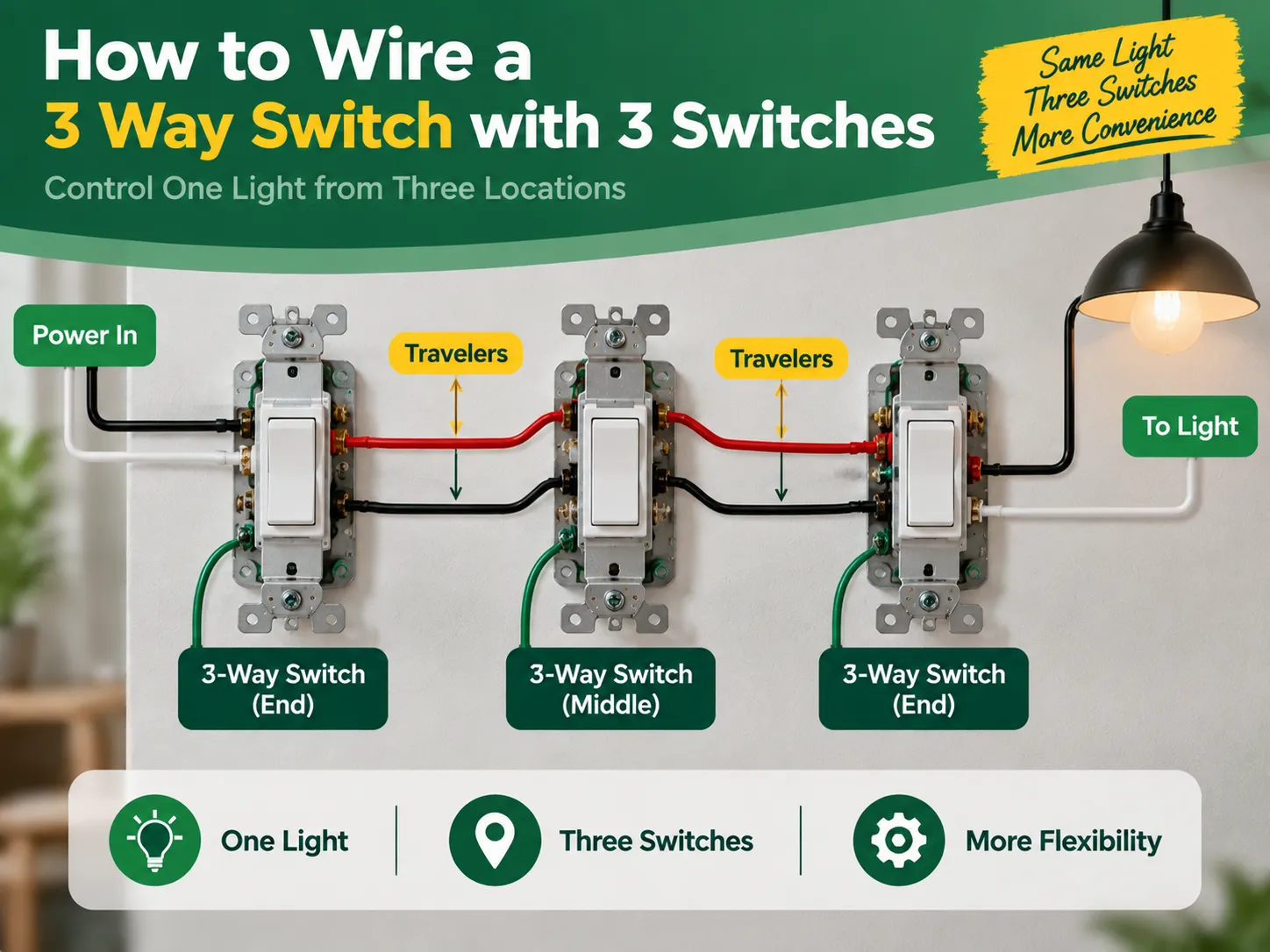
If you have a long room, hallway, or staircase and want to control one light switch from three different locations which are one at each end of the room and one in the middle. Then you are probably asking one of the most frequently asked and misunderstood questions about home wiring. The answer is surprising: […]

Het district Greenwich biedt een unieke combinatie van historische betekenis en moderniteit, wat te zien is in zijn historische locaties evenals zijn hedendaagse appartementen. In Greenwich bestaan het oude en het moderne in harmonie. Ondanks de aanwezigheid van de antieke gebouwen van de Georgische architectuur, kunnen ze worden geïnstalleerd met de […]
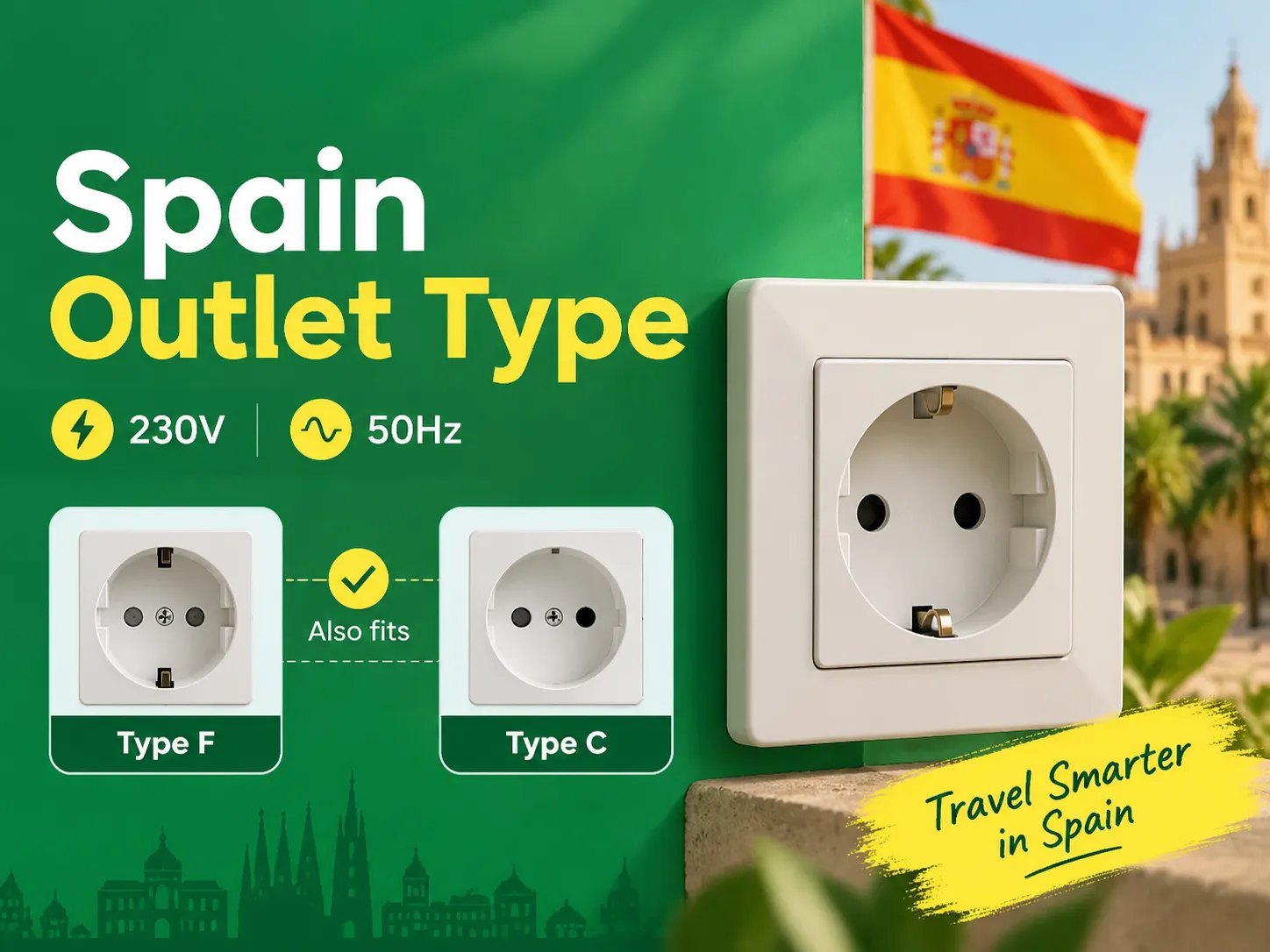
Als je de twee regels voor ronde pinnen kent, zul je ontdekken dat Spanje een van de eenvoudigste plaatsen in Europa is om je apparaten opgeladen en verbonden te houden, aangezien landen op het vasteland dezelfde stekkerdozen hebben. Degenen die vanuit het VK, de VS en Azië naar Spanje reizen, hebben slechts één adapter nodig. Dit artikel legt alles uit […]

 No.6 Tuozhan Road, Leshang Pioneer Park, Yueqingwan Bay Harbor, Yueqing stad, provincie Zhejiang


