

Jeśli masz długi pokój, korytarz lub schody i chcesz kontrolować jeden przełącznik światła z trzech różnych miejsc, które są po jednym na każdym końcu pokoju i jednym w środku. Wtedy prawdopodobnie zadajesz jedno z najczęściej zadawanych i źle rozumianych pytań dotyczących okablowania w domu. Odpowiedź jest zaskakująca: obwód nie jest okablowany przy użyciu trzech przełączników 3-drożnych. Zamiast tego, gdy obwód jest kontrolowany z trzech lokalizacji, wymaga dwóch przełączników 3-drożnych na obu końcach obwodu i jednego przełącznika 4-drożnego, który jest podłączony przy użyciu dwóch przewodników podróżnych. Ten artykuł omawia wszystko, co związane z koncepcją, narzędziami, krokami związanymi z okablowaniem, mapowaniem zacisków, procesem weryfikacji i specyfikacjami, aby uniknąć błędów, które najczęściej popełniają amatorzy.
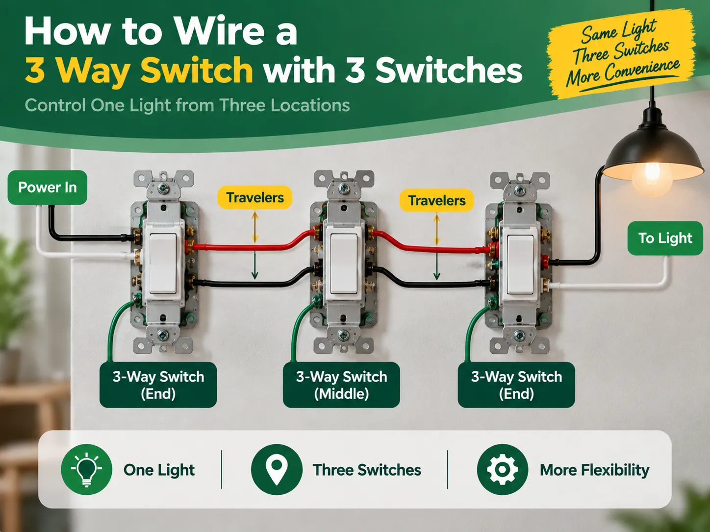
Odpowiedź jest krótka: Aby kontrolować jedno światło z trzech przełączników, potrzebujesz tylko dwóch przełączników 3-drożnych i jednego przełącznika 4-drożnego zamiast trzech przełączników 3-drożnych. Pierwszy przełącznik 3-drożny otrzymuje zasilanie przez swój wspólny zacisk i wysyła prąd przez dwa przewody podróżne. Przełącznik 4-drożny znajduje się w pobliżu środka i przełącza przewody podróżne na swoich zaciskach. Ostatni przełącznik 3-drożny odbiera przewody podróżne i ponownie wysyła przełączone zasilanie do lampy. Tak więc, gdy jeden z trzech przełączników jest włączony, światło jest włączone lub wyłączone niezależnie od pozycji pozostałych przełączników. Należy wyłączyć zasilanie z wyłącznika elektrycznego, sprawdzić to testerem, odpowiednio oznaczyć każdy przewód i postępować zgodnie z schematami podanymi poniżej.
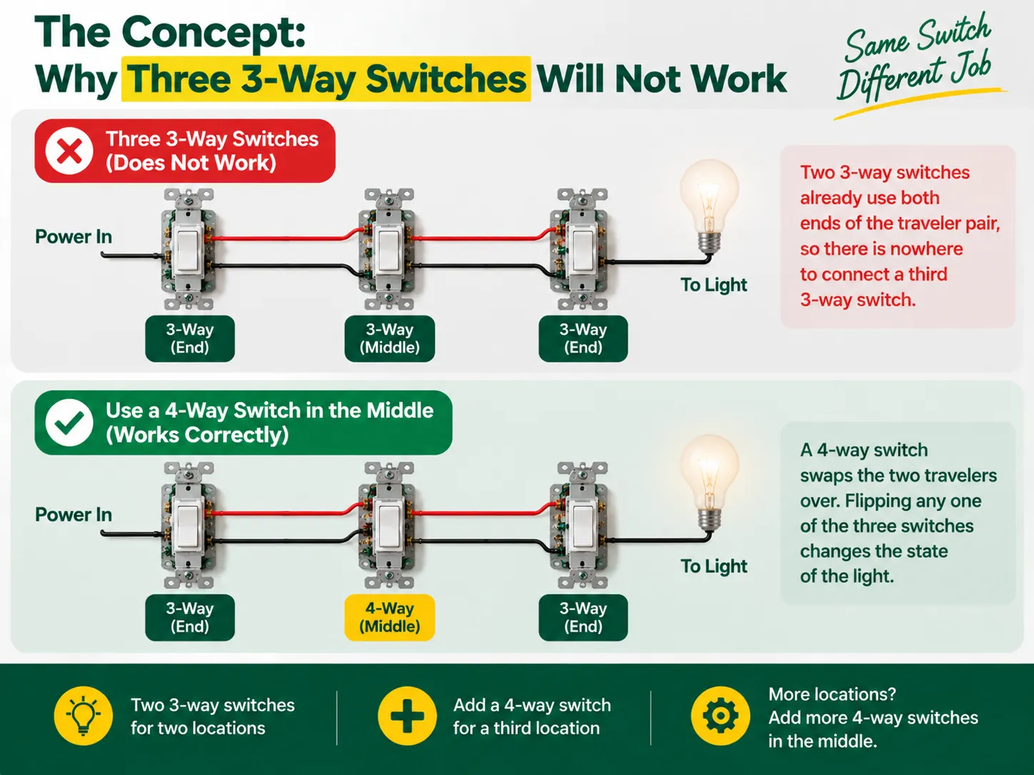
W przełącznikach 3-drożnych nie ma etykiet wskazujących “włączony” i “wyłączony”, ponieważ nie są one przełącznikami w prawdziwym sensie — działają jako przełącznik, który łączy dwa przewody podróżne. Zasilanie jest wysyłane do jednego z przewodów podróżnych przez pierwszy przełącznik 3-drożny, a drugi przełącznik 3-drożny wybiera, który przewód podróżny otrzymuje zasilanie i prowadzi do żarówki. W ten sposób dwaj partnerzy w tym procesie łączenia żarówki tworzą łańcuch, w którym wejścia przełącznika muszą pasować, aby żarówka się zaświeciła, więc światło gaśnie po prostu przez zmianę przełącznika.
Jednak gdy dodawane jest trzecie miejsce, można zauważyć, że tradycyjny system 3-way switches już nawiązał połączenie z obu końców kabla podróżnego, co uniemożliwia podłączenie dodatkowego przełącznika. Potrzebne jest zupełnie inne urządzenie zwane 4-way switch, które jest montowane pomiędzy dwoma podróżnymi gotowymi do zamiany. Z 4-way switch na miejscu, każdy przełącznik będzie mógł zmieniać status światła za każdym razem, gdy przełącznik jest włączany lub wyłączany, osiągając w ten sposób pożądany rezultat z trzech lokalizacji. Jeśli istnieje potrzeba podłączenia czwartego przełącznika, liczba urządzeń na miejscu wzrasta, ale zasada pozostaje ta sama.
Zanim zaczniesz, warto zrozumieć, jak cała rodzina przełączników pasuje do siebie — różnica między 1-way (jednobiegunowym), 2-way (3-way) i pośrednim (4-way) projektami oraz jak są one oznaczane na różnych rynkach, jest wyjaśniona w naszym przewodniku po różnych rodzajach przełączników elektrycznych.
| Pozycja | Specyfikacja |
|---|---|
| 3-przyciskowe przełączniki × 2 | Jeden dla końca zasilania, jeden dla końca światła; oba z terminalem “common” oraz dwoma terminalami podróżnymi |
| 4-przyciskowy przełącznik × 1 | Dla lokalizacji środkowej; cztery terminale (dwie pary podróżnych) |
| Przewód | 14 AWG w obwodzie 15 A lub 12 AWG w obwodzie 20 A (nigdy nie mieszaj rozmiarów w jednym obwodzie) |
| Kabel | 14/2 lub 12/2 (linia, neutralny, uziemienie) plus 14/3 lub 12/3 pomiędzy trzema skrzynkami dla dwóch podróżnych plus neutralny |
| Skrzynki i złącza przewodów | Skrzynki połączeniowe o odpowiednim rozmiarze, nakrętki przewodowe lub złącza dźwigniowe, taśma elektryczna |
| Narzędzia | Tester napięcia (bezkontaktowy i multimetr), wkrętaki, obcinaczki do przewodów, szczypce o cienkim końcu, latarka |
Najważniejszym rozwojem w ostatnich aktualizacjach przepisów elektrycznych jest wymóg, aby w każdej skrzynce przełącznika znajdował się przewód neutralny, aby w przyszłości można było obsługiwać inteligentne urządzenia. Jeśli to możliwe, użyj okablowania trzyprzewodowego (które zawiera czerwonego podróżnego) i poprowadź przewód neutralny przez wszystkie skrzynki przełączników. Jeśli Twój projekt polega na wymianie starych przełączników, a nie na nowym okablowaniu, dyscyplina sprawdzania skrzynek i wymiany w naszym przewodnik wymiany włącznika światła ma zastosowanie w każdej lokalizacji.
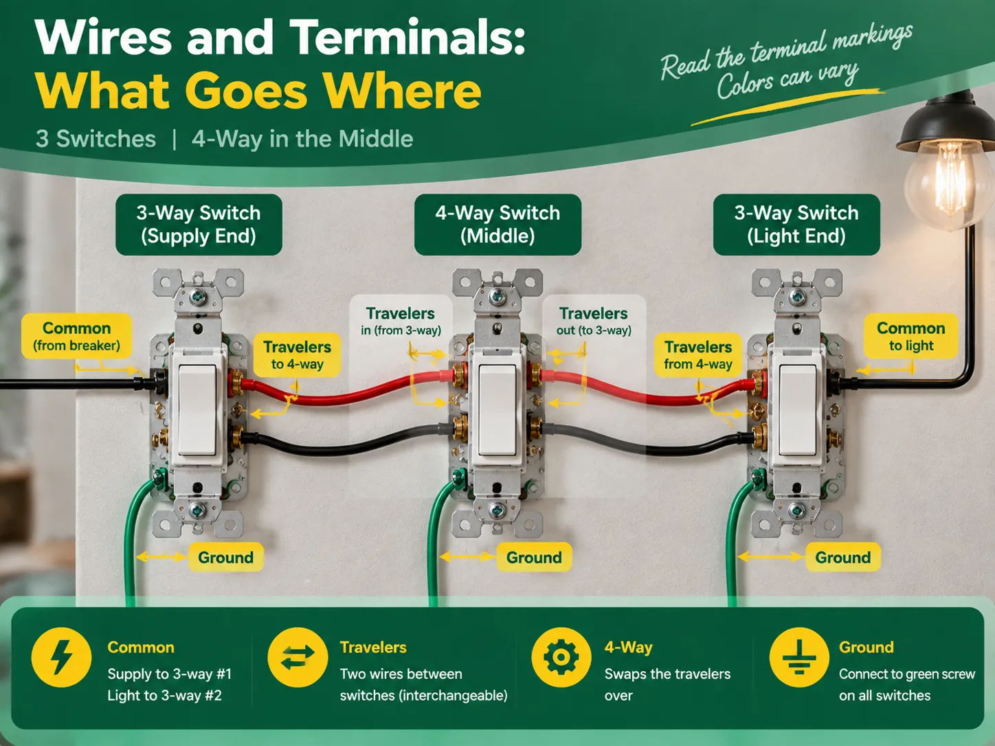
Pomimo faktu, że oznaczenia terminali są takie same dla wysokiej jakości przełączników, kolory różnią się w zależności od producenta, dlatego zawsze zaleca się sprawdzenie tekstu na urządzeniu. Powszechnie akceptowana zasada mówi, że:
| Zasada | Przełącznik | Zacisk | Co łączy |
|---|---|---|---|
| Common (linia) | 3-way #1 (koniec zasilania) | Ciemniejsza śruba lub oznaczona COMMON / C | Przewód zasilający (z wyłącznika) |
| Travelers | 3-przyciskowy #1 | Dwie pozostałe śruby (mosiężne lub oznaczone 1 i 2) | Dwa przewody podróżne prowadzące do 4-way |
| Para podróżnych w | 4-way (środkowy) | Jedna para terminali | Podróżni pochodzący z 3-way #1 |
| Para podróżnych na zewnątrz | Krzyżowy | Druga para terminali | Podróżni kontynuujący do 3-way #2 |
| Travelers | 3-way #2 (koniec światła) | Dwie śruby podróżne | Podróżni pochodzący z 4-way |
| Common (load) | 3-way #2 | Common terminal | The switched wire running to the light |
The two traveler wires should preferably be colored the same (for example, the black wire and red wire in cable 14/3 for the US or two identical wires in the three-core-and-earth UK cable). In this case, it is good news to know that travelers may be changes without any concerns, provided that they remain unchanged when passing the 4-way switch. However, the common terminal is not interchangeable.
Act with deliberation, one compartment at a time, and treat every wire as hot until you eliminate the doubt.
The verification comes in three steps during which the two common wiring mistakes can be identified – incorrect wiring and crossed traveler continuity.
Almost all unsuccessful three-switch circuits can be attributed to one of the following errors:
Almost none of the aforementioned mistakes can escape being revealed during continuity check; hence “the checking part” is so important.
No, you will never have three 3-way switches in one circuit. You need two 3-way switches to control one light via three power sources, plus one 4-way switch in the middle. To add more than three switches to control the light, you will add another 4-way switch between the 3-way switches.
There are five most practial mistakes: using three 3-way switches instead of two 3-way and one 4-way switch, incorrectly connecting the power source to the traveler terminal instead of the common terminal, switching the neutral instead of connecting it through the wires, incorrectly connecting the travelers in the 4-way switch, and skipping the grounding and labelling of the wires. All these mistakes can be detected by a continuity test before turning the power on.
The 3-way switch has one dark marked terminal (the common terminal) to which the wire from the hot supply at one end and wire from the light at that end of the circuit should be connected. The two brass traveler terminals are to take two wires connecting the 3-way switch with the 4-way one. In the 4-way switch, one pair of traveler wires is to be connected to one pair of terminals.
If these three lights are to be switched on/off simultaneously from all three locations, then the multi-way circuit needs to be made in the same way but the lights have to be connected in parallel from the load-end common terminal. If each of the switches from each location is to control its own light, it is not a multi-way but three independent circuits.
The process of wiring a single light to three switches is an interesting illustration of how understanding the basics leads to effective electrical project completion. In this case, the key concept is the fact that a multiway circuit consists of two 3-way “selector” switches and one or more 4-way “mutator” switches in between. To create a three-way circuit one simply requires two 3-way switches and a 4-way switch wired in a way so that the line feeds the common terminal of the first 3-way switch, travelers run through the 4-way switch, and the common terminal of the last 3-way switch leads to the light. To complete the wiring project correctly, one must do the following: follow the terminal configuration mapping, wire the neutrals straight passing through all boxes, ground components as needed, mark the load and line terminals, and look up for a continuity check on the circuit after its completion. It is also important to remember that only quality switches should be used in the project and that the best switches come from reliable manufacturers. This specific aspect of the process is discussed in detail in the articles on the choice of an electrical switch and socket manufacturer since all the techniques used to check the quality of electrical switches and connectors are the ones used in the manufacturing process of electrical devices.
If you have a long room, hallway, or staircase and want to control one light switch from three different locations which are one at each end of the room and one in the middle. Then you are probably asking one of the most frequently asked and misunderstood questions about home wiring. The answer is surprising: […]
Dzielnica Greenwich oferuje unikalne połączenie historycznego znaczenia i nowoczesności, co można zobaczyć w jej zabytkach oraz współczesnych budynkach mieszkalnych. W Greenwich stare i nowoczesne współistnieją w harmonii. Pomimo obecności antycznych budynków architektury georgiańskiej, mogą być one zainstalowane z […]
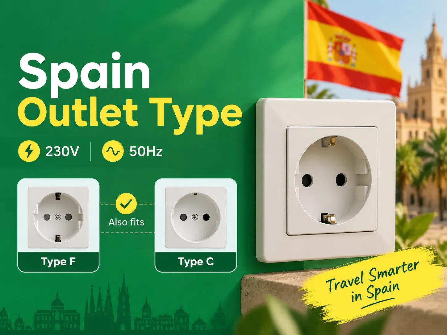
Jeśli znasz zasady dotyczące dwóch okrągłych pinów, odkryjesz, że Hiszpania jest jednym z najprostszych miejsc w Europie, aby utrzymać swoje urządzenia naładowane i podłączone, ponieważ kraje na kontynencie mają te same gniazdka. Osoby podróżujące do Hiszpanii z Wielkiej Brytanii, USA i Azji potrzebują tylko jednego adaptera. Ten artykuł wyjaśnia wszystko […]

 Droga Tuozhan nr 6, Leshang Pioneer Park, port Yueqingwan Bay, miasto Yueqing, prowincja Zhejiang


