

Om du har ett långt rum, en korridor eller en trappa och vill styra en lampbrytare från tre olika platser som är en i varje ände av rummet och en i mitten. Då ställer du förmodligen en av de mest frekvent ställda och missförstådda frågorna om hemmakoppling. Svaret är överraskande: kretsen är inte kopplad med tre 3-vägsbrytare. Istället, när en krets styrs från tre platser, krävs två 3-vägsbrytare i båda ändar av kretsen och en fyrvägsbrytare som kopplas med de två resande ledningarna. Denna artikel diskuterar allt som rör konceptet, verktyg, steg involverade i kopplingen, terminalkartläggning, verifieringsprocess och specifikationer för att undvika fel som oftast görs av amatörer.
Svaret är kort: För att styra en lampa från tre brytare behöver du bara två 3-vägsbrytare och en fyrvägsbrytare istället för tre 3-vägsbrytare. Den första 3-vägsbrytaren får den heta strömförsörjningen genom sin gemensamma terminal och skickar strömmen ut genom de två resande kablarna. Fyrvägsbrytaren är nära mitten och växlar resande vid sina terminaler. Den sista 3-vägsbrytaren tar emot de resande kablarna och skickar återigen den växlade heta till lampan. Så när en av de tre brytarna slås på, slås lampan av eller på oavsett positionen för de andra brytarna. Du bör stänga av strömmen från elbrytaren, kontrollera den med en tester, märka varje kabel korrekt och följa schemat nedan.
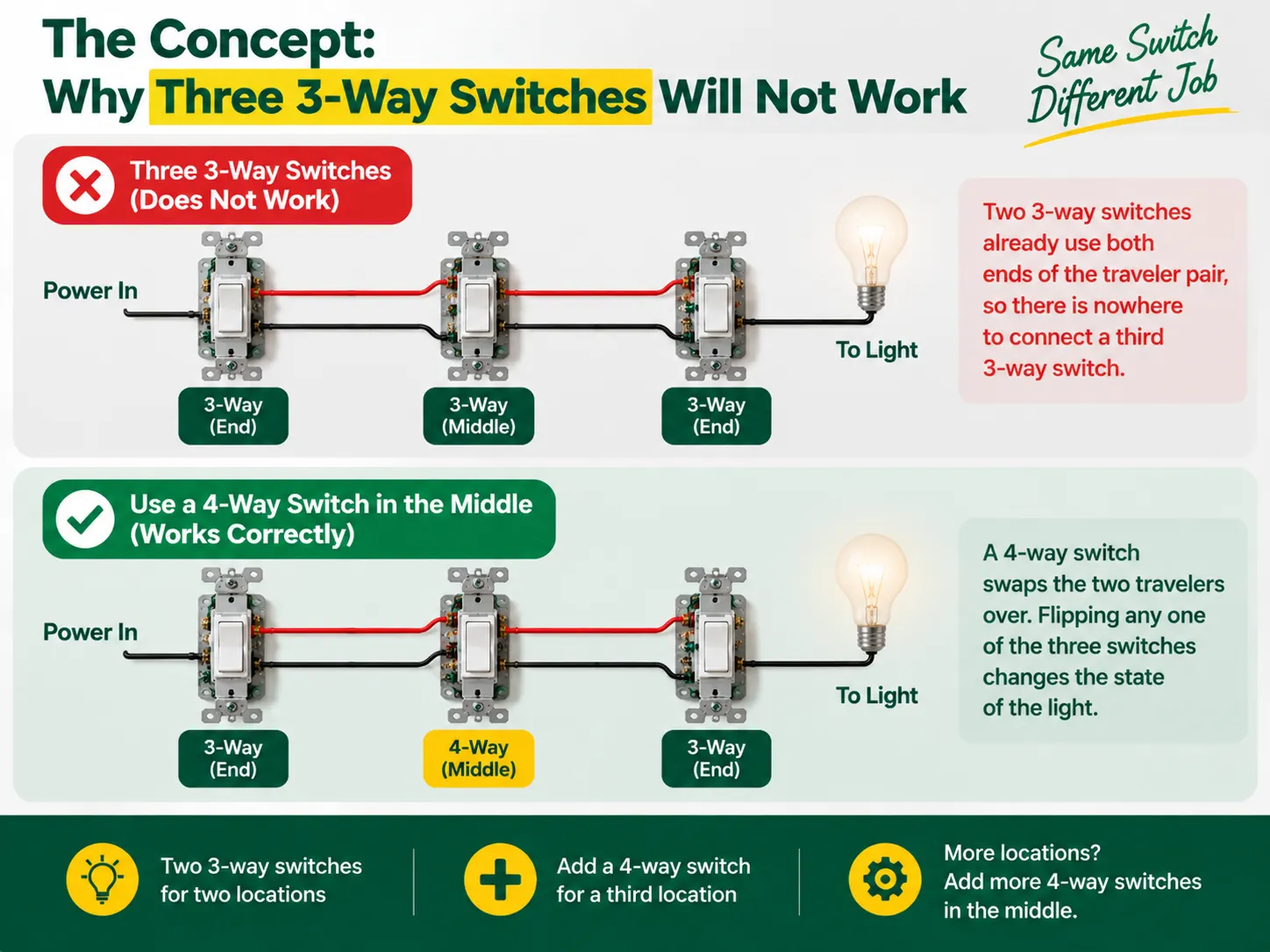
Det finns inga etiketter som indikerar “på” och “av” i 3-vägsbrytare eftersom de inte är brytare i sann mening — de fungerar som en brytare som kopplar två resande kablar. Strömmen skickas till en av de resande av den första 3-vägsbrytaren och den andra 3-vägsbrytaren väljer vilken resande som får strömmen och leder till glödlampan. Således bildar de två partnerna i denna process av att koppla glödlampan en kedja, där brytarens ingångar måste matcha för att glödlampan ska lysa, så lampan släcks helt enkelt genom att ändra brytaren.
Men när en tredje plats läggs till, tenderar man att se att det traditionella systemet med 3-vägsomkopplare redan har etablerat en anslutning med båda ändar av resen kabeln, vilket förhindrar att en ytterligare omkopplare kan kopplas dit. Vad som behövs är en helt annan enhet som kallas en 4-vägsomkopplare, som monteras mellan två resor redo att byta dem. Med 4-vägsomkopplaren på plats kommer varje omkopplare att kunna ändra statusen på ljuset varje gång omkopplaren slås på eller av, vilket uppnår ett resultat som önskas från tre platser. Om det finns behov av att ansluta den fjärde omkopplaren, ökar antalet enheter på plats men principen är densamma.
Innan du börjar är det värt att förstå hur hela omkopplarfamiljen passar ihop — skillnaden mellan 1-vägs (enkelt pol), 2-vägs (3-vägs) och mellanliggande (4-vägs) konstruktioner, och hur de är märkta på olika marknader, förklaras i vår guide till de olika typerna av elektriska strömbrytare.
| Artikel | Specifikation |
|---|---|
| 3-vägsomkopplare × 2 | En för försörjningsänden, en för ljusänden; båda med en “gemensam” terminal plus två reseterminaler |
| 4-vägsomkopplare × 1 | För den mittersta platsen; fyra terminaler (två par av resor) |
| Kabel | 14 AWG på en 15 A-krets eller 12 AWG på en 20 A-krets (blanda aldrig storlekar på en krets) |
| Kabel | 14/2 eller 12/2 (linje, neutral, jord) plus 14/3 eller 12/3 mellan de tre lådorna för de två resorna plus neutral |
| Lådor och kabelkopplingar | Rätt storlek på kopplingslådor, kabelskruvar eller spakkopplingar, elektrisk tejp |
| Verktyg | Spänningsprovare (icke-kontakt och multimeter), skruvmejslar, kabelskalare, näbbtång, ficklampa |
Den mest anmärkningsvärda utvecklingen i de senaste elektriska koduppdateringarna är ett krav på att en neutral kabel ska ingå i varje omkopplarlåda så att smarta enheter kan stödjas i framtiden. Om möjligt, använd tre-kabelkoppling (som inkluderar den röda resan) och dra en neutral kabel genom alla omkopplarlådor. Om ditt projekt handlar om att byta ut gamla omkopplare snarare än ny kabeldragning, tillämpas boxkontroll och utbytesdisciplin i vår guiden för byte av ljusströmbrytare tillämpas på varje plats.
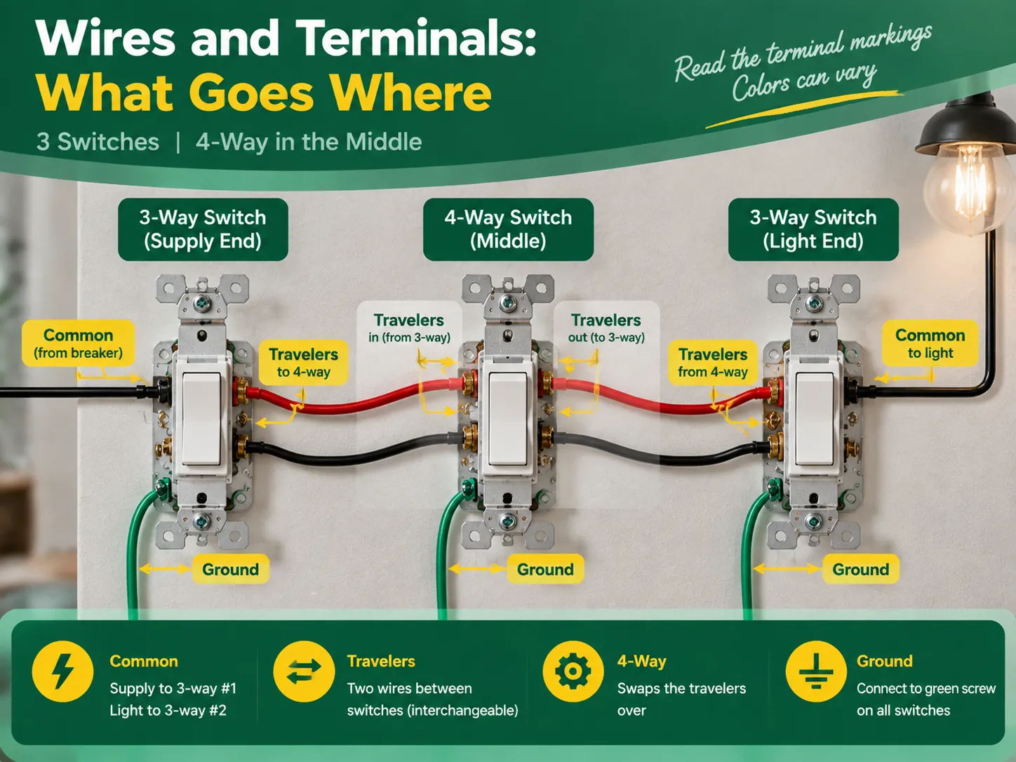
Trots att terminalbeteckningarna är desamma för högkvalitativa omkopplare, skiljer sig färgerna beroende på tillverkaren, och det är därför alltid rekommenderat att kontrollera texten på apparaten. En allmänt accepterad regel säger att:
| Regel | Växla | Terminal | Vad som kopplar |
|---|---|---|---|
| Gemensam (linje) | 3-vägs #1 (försörjningsände) | Mörkare skruv, eller märkt GEMENSAM / C | Den heta försörjningskabeln (från brytaren) |
| Travelers | 3-vägs #1 | De två återstående skruvarna (mässing, eller märkta 1 och 2) | De två resande kablarna som går till 4-vägsomkopplaren |
| Reseparet in | 4-vägs (mitten) | Ett par terminaler | Resorna som kommer från 3-vägs #1 |
| Reseparet ut | 4-vägs | Det andra paret av terminaler | Resorna som fortsätter till 3-vägs #2 |
| Travelers | 3-vägs #2 (ljusände) | Två reseskruvar | Resorna som kommer från 4-vägsomkopplaren |
| Common (load) | 3-way #2 | Common terminal | The switched wire running to the light |
The two traveler wires should preferably be colored the same (for example, the black wire and red wire in cable 14/3 for the US or two identical wires in the three-core-and-earth UK cable). In this case, it is good news to know that travelers may be changes without any concerns, provided that they remain unchanged when passing the 4-way switch. However, the common terminal is not interchangeable.
Act with deliberation, one compartment at a time, and treat every wire as hot until you eliminate the doubt.
The verification comes in three steps during which the two common wiring mistakes can be identified – incorrect wiring and crossed traveler continuity.
Almost all unsuccessful three-switch circuits can be attributed to one of the following errors:
Almost none of the aforementioned mistakes can escape being revealed during continuity check; hence “the checking part” is so important.
No, you will never have three 3-way switches in one circuit. You need two 3-way switches to control one light via three power sources, plus one 4-way switch in the middle. To add more than three switches to control the light, you will add another 4-way switch between the 3-way switches.
There are five most practial mistakes: using three 3-way switches instead of two 3-way and one 4-way switch, incorrectly connecting the power source to the traveler terminal instead of the common terminal, switching the neutral instead of connecting it through the wires, incorrectly connecting the travelers in the 4-way switch, and skipping the grounding and labelling of the wires. All these mistakes can be detected by a continuity test before turning the power on.
The 3-way switch has one dark marked terminal (the common terminal) to which the wire from the hot supply at one end and wire from the light at that end of the circuit should be connected. The two brass traveler terminals are to take two wires connecting the 3-way switch with the 4-way one. In the 4-way switch, one pair of traveler wires is to be connected to one pair of terminals.
If these three lights are to be switched on/off simultaneously from all three locations, then the multi-way circuit needs to be made in the same way but the lights have to be connected in parallel from the load-end common terminal. If each of the switches from each location is to control its own light, it is not a multi-way but three independent circuits.
The process of wiring a single light to three switches is an interesting illustration of how understanding the basics leads to effective electrical project completion. In this case, the key concept is the fact that a multiway circuit consists of two 3-way “selector” switches and one or more 4-way “mutator” switches in between. To create a three-way circuit one simply requires two 3-way switches and a 4-way switch wired in a way so that the line feeds the common terminal of the first 3-way switch, travelers run through the 4-way switch, and the common terminal of the last 3-way switch leads to the light. To complete the wiring project correctly, one must do the following: follow the terminal configuration mapping, wire the neutrals straight passing through all boxes, ground components as needed, mark the load and line terminals, and look up for a continuity check on the circuit after its completion. It is also important to remember that only quality switches should be used in the project and that the best switches come from reliable manufacturers. This specific aspect of the process is discussed in detail in the articles on the choice of an electrical switch and socket manufacturer since all the techniques used to check the quality of electrical switches and connectors are the ones used in the manufacturing process of electrical devices.
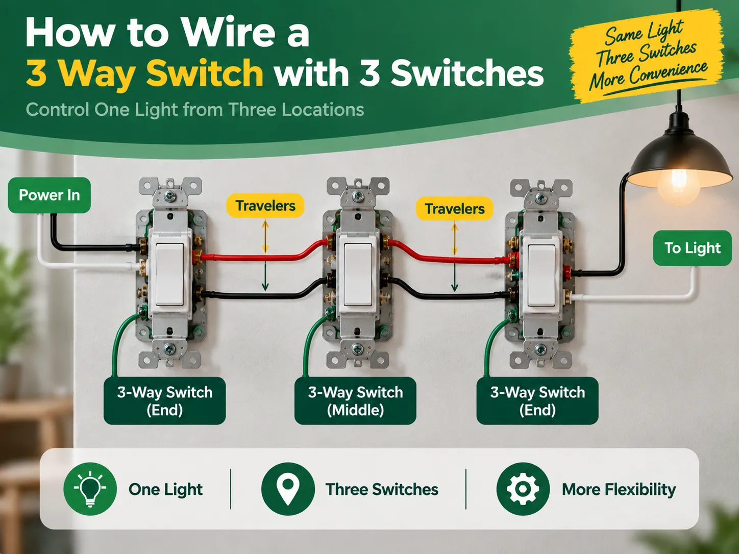
If you have a long room, hallway, or staircase and want to control one light switch from three different locations which are one at each end of the room and one in the middle. Then you are probably asking one of the most frequently asked and misunderstood questions about home wiring. The answer is surprising: […]

Distriktet Greenwich erbjuder en unik kombination av historisk betydelse och modernitet, vilket kan ses i dess historiska platser såväl som i dess moderna lägenhetsbyggnader. I Greenwich samexisterar det gamla och det moderna i harmoni. Trots närvaron av de antika byggnaderna i den georgianska arkitekturen, kan de installeras med […]
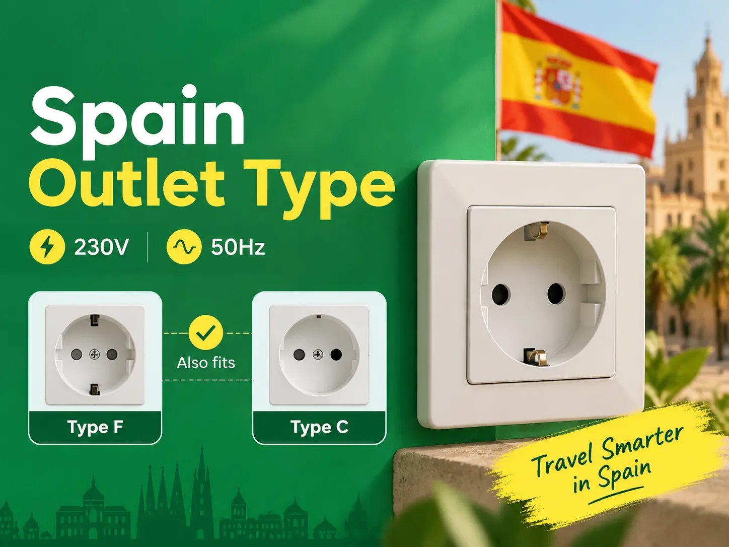
Om du känner till de två rundstiftsreglerna, kommer du att upptäcka att Spanien är en av de enklaste platserna i Europa för att hålla dina enheter laddade och anslutna, eftersom länderna på fastlandet har samma kontaktdon. De som reser till Spanien från Storbritannien, USA och Asien behöver bara en enda adapter. Denna artikel förklarar allt […]

 No.6 Tuozhan Road, Leshang Pioneer Park, Yueqingwan Bay Harbor, Yueqing stad, Zhejiang-provinsen


