

Якщо у вас довгий кімната, коридор або сходи і ви хочете керувати одним вимикачем світла з трьох різних місць, які знаходяться по одному з кожного кінця кімнати і один посередині. Тоді ви, напевно, ставите одне з найчастіше задаваних і неправильно зрозумілих питань про домашнє електропостачання. Відповідь дивовижна: схема не підключена за допомогою трьох трьохпозиційних вимикачів. Натомість, коли схема контролюється з трьох місць, вона вимагає два 3-позиційні вимикачі на обох кінцях схеми та один чотирипозиційний вимикач, який підключається за допомогою двох провідників подорожі. Ця стаття обговорює все, що стосується концепції, інструментів, етапів підключення, картування клем, процесу перевірки та специфікацій, щоб уникнути помилок, які зазвичай роблять аматори.
Відповідь коротка: щоб керувати одним світлом з трьох вимикачів, вам потрібно лише два трьохпозиційні вимикачі та один чотирипозиційний вимикач замість трьох трьохпозиційних вимикачів. Перший трьохпозиційний вимикач отримує гаряче живлення через свій загальний клем і відправляє струм через два провідники подорожі. Чотирипозиційний вимикач знаходиться поблизу центру і перемикає провідники на своїх клемах. Останній трьохпозиційний вимикач отримує провідники подорожі і знову відправляє перемкнуте гаряче живлення до світла. Таким чином, коли один з трьох вимикачів увімкнено, світло вмикається або вимикається незалежно від положення інших вимикачів. Вам слід вимкнути живлення від електричного автомату, перевірити його тестером, правильно підписати кожен провід і дотримуватися схем, наведених нижче.
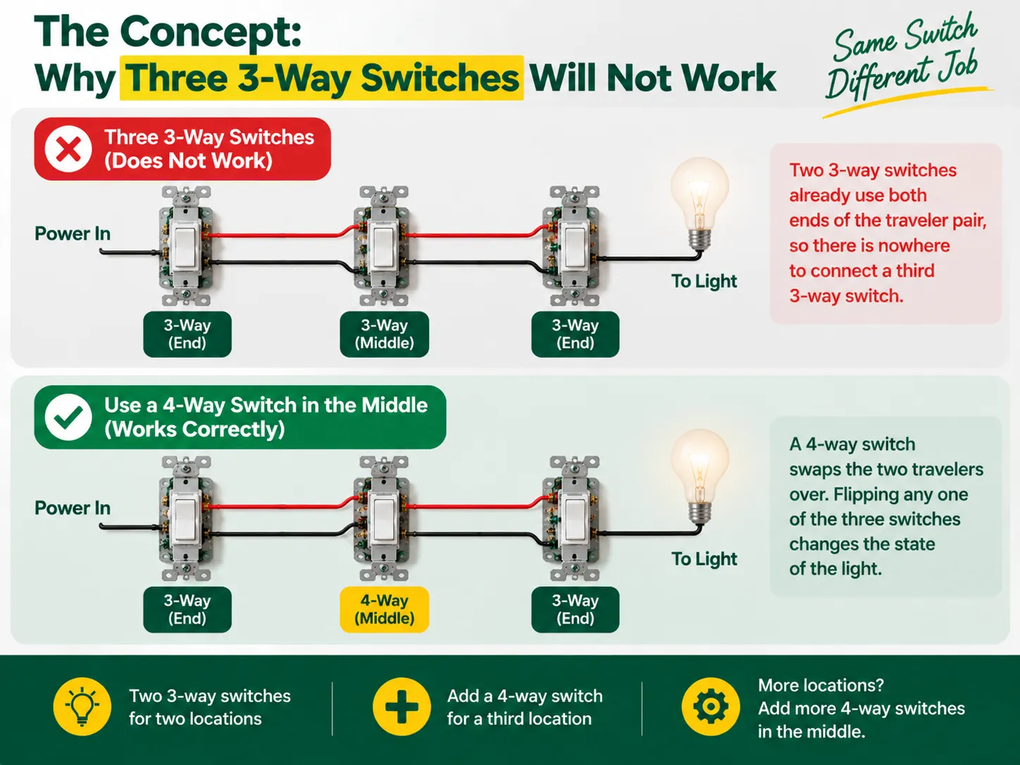
У 3-позиційних вимикачах немає міток, які вказують “увімкнено” та “вимкнено”, оскільки вони не є вимикачами в істинному сенсі — вони функціонують як вимикач, який з'єднує два провідники подорожі. Живлення надсилається до одного з провідників подорожі першим 3-позиційним вимикачем, а інший 3-позиційний вимикач вибирає, який провідник отримує живлення і веде до лампочки. Таким чином, два партнери в цьому процесі з'єднання лампочки формують ланцюг, де входи вимикача повинні збігатися, щоб лампочка загорілася, тому світло вимикається просто зміною вимикача.
Однак, коли додається третє місце, можна помітити, що традиційна система 3-way перемикачів вже встановила з'єднання з обома кінцями проводу подорожі, що унеможливлює підключення додаткового перемикача. Те, що потрібно, — це зовсім інший пристрій, званий 4-way перемикачем, який встановлюється між двома провідниками, готовими до обміну. З 4-way перемикачем на місці, кожен перемикач зможе змінювати статус світла щоразу, коли перемикач вмикається або вимикається, досягаючи таким чином бажаного результату з трьох місць. Якщо виникає потреба в підключенні четвертого перемикача, кількість пристроїв на місці збільшується, але принцип залишається тим самим.
Перед початком варто зрозуміти, як вся родина перемикачів поєднується — різниця між 1-way (однополюсними), 2-way (3-way) та проміжними (4-way) конструкціями, а також як вони маркуються на різних ринках, пояснюється в нашій посібнику з різних видів електричних перемикачів.
| Предмет | Специфікація |
|---|---|
| 3-way перемикачі × 2 | Один для кінця живлення, один для кінця світла; обидва з “загальним” терміналом плюс два термінали подорожі |
| 4-way перемикач × 1 | Для середнього місця; чотири термінали (дві пари подорожей) |
| Провід | 14 AWG на 15 A колі або 12 AWG на 20 A колі (ніколи не змішуйте розміри на одному колі) |
| Кабель | 14/2 або 12/2 (фаза, нейтраль, заземлення) плюс 14/3 або 12/3 між трьома коробками для двох подорожей плюс нейтраль |
| Коробки та з'єднувачі проводів | Коректні за розміром з'єднувальні коробки, гайки для проводів або з'єднувачі з важелем, електрична стрічка |
| Інструменти | Тестер напруги (безконтактний та мультиметр), викрутки, стрипери для проводів, плоскогубці, ліхтарик |
Найбільш помітним розвитком у недавніх оновленнях електричного коду є вимога, щоб нейтральний кабель був включений у кожну коробку перемикача, щоб у майбутньому можна було підтримувати розумні пристрої. Якщо можливо, використовуйте трьохпровідне з'єднання (яке включає червоний провідник) і прокладіть нейтральний кабель через усі коробки перемикачів. Якщо ваш проект полягає в заміні старих перемикачів, а не в новій проводці, дисципліна перевірки коробок і заміни в нашій посібник з заміни вимикача світла застосовується в кожному місці.
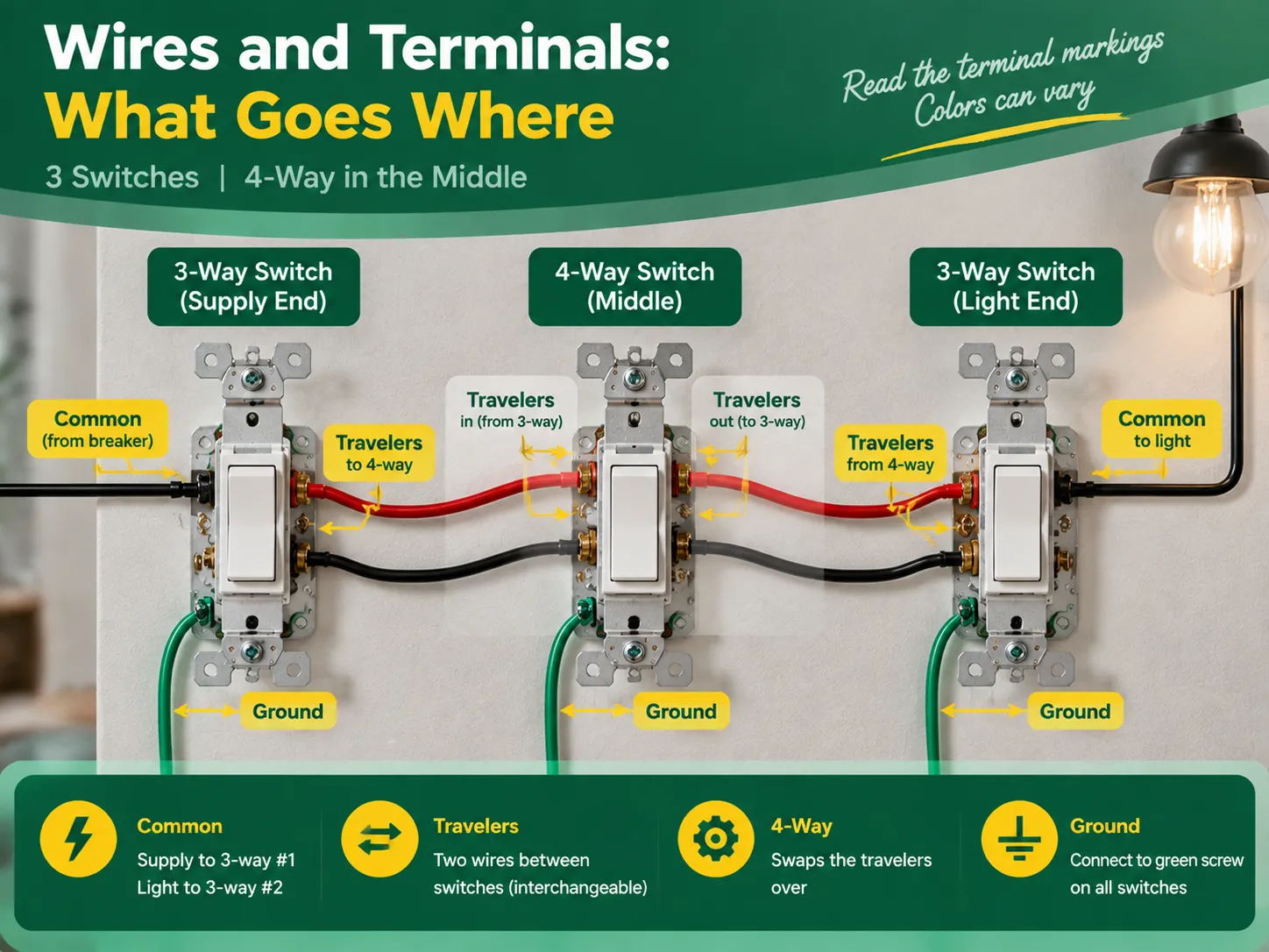
Незважаючи на те, що позначення терміналів однакові для високоякісних перемикачів, кольори відрізняються в залежності від виробника, тому завжди доцільно перевіряти текст на пристрої. Загальновизнане правило стверджує, що:
| Правило | Перемикач | Термінал | Що з'єднує |
|---|---|---|---|
| Загальний (фаза) | 3-way #1 (кінець живлення) | Темніший гвинт або позначений COMMON / C | Провід гарячого живлення (від автоматичного вимикача) |
| Travelers | 3-ходовий #1 | Два залишкові гвинти (латунні або позначені 1 і 2) | Два провідники подорожі, що йдуть до 4-way |
| Пара подорожей у | 4-way (середина) | Одна пара терміналів | Провідники, що йдуть від 3-way #1 |
| Пара подорожей вихід | 4-позиційний | Інша пара терміналів | Провідники, що продовжують до 3-way #2 |
| Travelers | 3-way #2 (кінець світла) | Два гвинти подорожі | Провідники, що йдуть від 4-way |
| Common (load) | 3-way #2 | Common terminal | The switched wire running to the light |
The two traveler wires should preferably be colored the same (for example, the black wire and red wire in cable 14/3 for the US or two identical wires in the three-core-and-earth UK cable). In this case, it is good news to know that travelers may be changes without any concerns, provided that they remain unchanged when passing the 4-way switch. However, the common terminal is not interchangeable.
Act with deliberation, one compartment at a time, and treat every wire as hot until you eliminate the doubt.
The verification comes in three steps during which the two common wiring mistakes can be identified – incorrect wiring and crossed traveler continuity.
Almost all unsuccessful three-switch circuits can be attributed to one of the following errors:
Almost none of the aforementioned mistakes can escape being revealed during continuity check; hence “the checking part” is so important.
No, you will never have three 3-way switches in one circuit. You need two 3-way switches to control one light via three power sources, plus one 4-way switch in the middle. To add more than three switches to control the light, you will add another 4-way switch between the 3-way switches.
There are five most practial mistakes: using three 3-way switches instead of two 3-way and one 4-way switch, incorrectly connecting the power source to the traveler terminal instead of the common terminal, switching the neutral instead of connecting it through the wires, incorrectly connecting the travelers in the 4-way switch, and skipping the grounding and labelling of the wires. All these mistakes can be detected by a continuity test before turning the power on.
The 3-way switch has one dark marked terminal (the common terminal) to which the wire from the hot supply at one end and wire from the light at that end of the circuit should be connected. The two brass traveler terminals are to take two wires connecting the 3-way switch with the 4-way one. In the 4-way switch, one pair of traveler wires is to be connected to one pair of terminals.
If these three lights are to be switched on/off simultaneously from all three locations, then the multi-way circuit needs to be made in the same way but the lights have to be connected in parallel from the load-end common terminal. If each of the switches from each location is to control its own light, it is not a multi-way but three independent circuits.
The process of wiring a single light to three switches is an interesting illustration of how understanding the basics leads to effective electrical project completion. In this case, the key concept is the fact that a multiway circuit consists of two 3-way “selector” switches and one or more 4-way “mutator” switches in between. To create a three-way circuit one simply requires two 3-way switches and a 4-way switch wired in a way so that the line feeds the common terminal of the first 3-way switch, travelers run through the 4-way switch, and the common terminal of the last 3-way switch leads to the light. To complete the wiring project correctly, one must do the following: follow the terminal configuration mapping, wire the neutrals straight passing through all boxes, ground components as needed, mark the load and line terminals, and look up for a continuity check on the circuit after its completion. It is also important to remember that only quality switches should be used in the project and that the best switches come from reliable manufacturers. This specific aspect of the process is discussed in detail in the articles on the choice of an electrical switch and socket manufacturer since all the techniques used to check the quality of electrical switches and connectors are the ones used in the manufacturing process of electrical devices.
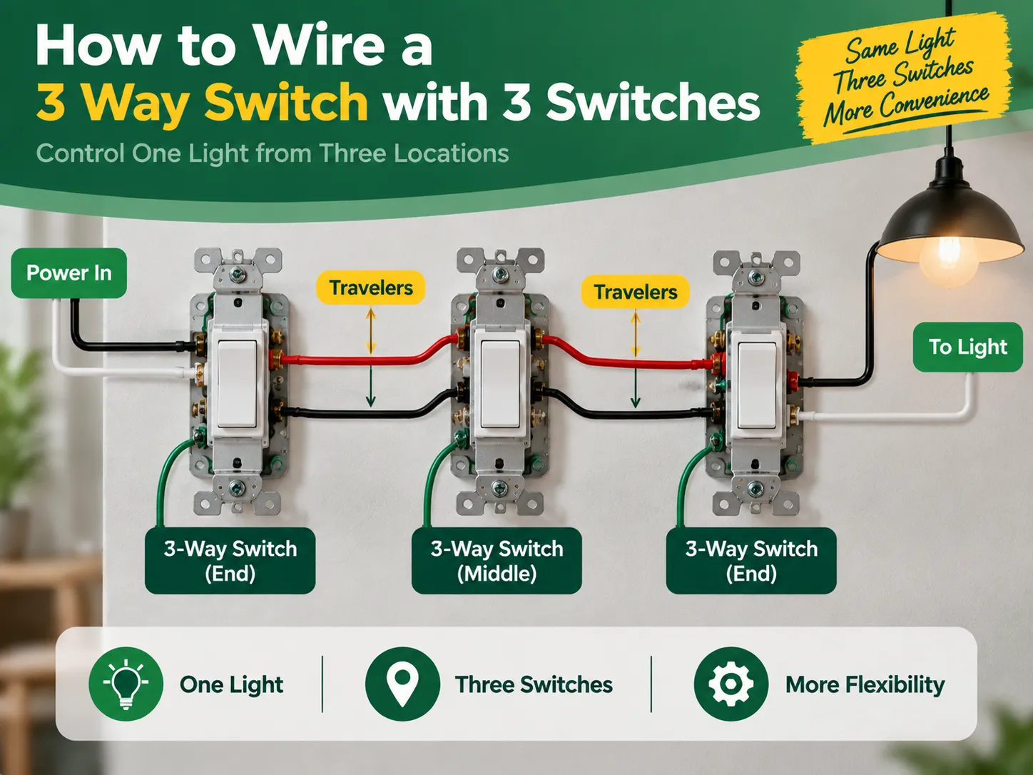
If you have a long room, hallway, or staircase and want to control one light switch from three different locations which are one at each end of the room and one in the middle. Then you are probably asking one of the most frequently asked and misunderstood questions about home wiring. The answer is surprising: […]

Район Грінвіча пропонує унікальне поєднання історичної важливості та сучасності, що можна побачити в його історичних пам'ятках, а також у сучасних житлових будинках. У Грінвічі старе та сучасне співіснують у гармонії. Незважаючи на наявність антикварних будівель георгіанської архітектури, їх можна обладнати […]
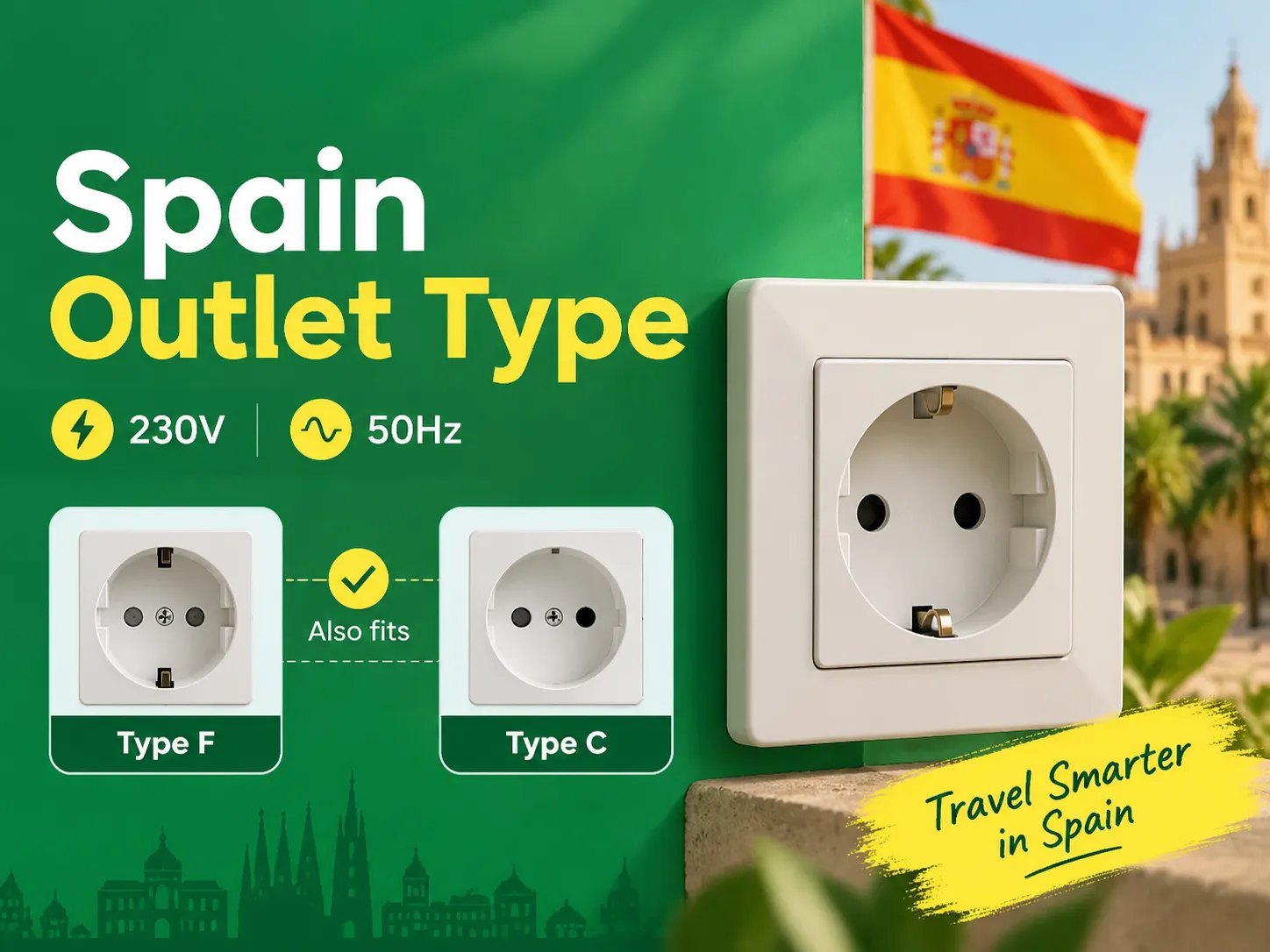
Якщо ви знаєте правила двох круглих контактів, ви виявите, що Іспанія є одним з найпростіших місць в Європі для заряджання та підключення ваших пристроїв, оскільки країни на континенті мають однакові розетки. Ті, хто подорожує до Іспанії з Великої Британії, США та Азії, потребують лише одного адаптера. Ця стаття пояснює все […]

 No.6 Tuozhan Road, Leshang Pioneer Park, Yueqingwan Bay Harbor, Yueqing city, Zhejiang Province


