

Quick answer: On North American floor plans, an electrical outlet symbol is commonly shown as a small circle with one or more lines extending from it. A duplex receptacle typically uses two parallel lines. Additional letters, shapes, or shading can identify features such as GFCI protection, floor mounting, or isolated grounding. Always check the drawing legend because symbols can vary between projects and standards.
Electrical symbols are shorthand used on floor plans, wiring diagrams, and other technical drawings. Rather than spending time creating a realistic picture of every outlet or electrical component, the designer uses a symbol to represent it.
This makes a large drawing easier to read and gives architects, engineers, contractors, and installers a common reference during a project.
However, not every drawing utilizes the same symbol system. For example, international electrical diagrams commonly use IEC symbols. Meanwhile, ANSI/NECA-style conventions are typically followed for construction drawings in North America. The conventions can also be modified for individual projects.
That’s why the legend on the drawing matters. It tells you exactly what the symbols and abbreviations mean on that particular set of plans.
A wall receptacle on a typical architectural North American floor plan is denoted by a small circle placed against the wall line. You can identify the receptacle configuration through the lines extending from or through the circle.
For example, a circle with two parallel lines indicates that it is a duplex receptacle. Floor outlets are typically distinguished by using an outlet symbol inside a square. If it’s a circle with just one parallel line, it’s likely a single receptacle.
Other electrical outlet symbols and meanings rely on using letters or making minor changes in the basic symbol. Switched receptacle manufacturers may also use a control line that connects it to the corresponding switch.
However, it’s not right to consider that adding more likes always reveals the number of receptacles. It doesn’t, because quadruplex and triplex arrangements can use abbreviations like QUAD and other notations from the drawing legend. These are common drafting conventions and not rules that you can apply to each electric drawing.
The first step is to locate the outlet symbol on the floor plan and see its position and the number and letters beside it. A wall outlet is commonly indicated by a receptacle symbol positioned against a wall. If you see a symbol inside a square, you’re most probably looking at a floor outlet instead.
When it comes to letters, different phrases have different meanings. IG means it can identify an isolated-ground receptacle. GFCI typically indicates ground-fault protection. WP may imply that the outlet is waterproof. Some outlets may also have the mounting height or circuit number noted nearby.
Keep in mind that the meaning of every abbreviation can vary from project to project. Plus, some details may only appear in a device schedule rather than be listed beside the outlet symbol. Hence, checking the drawing legend is just as critical as knowing how to read the symbol.
A switched receptacle needs an additional marking so the installer knows which outlet is controlled by a switch.
Depending on the drawing convention, part of a duplex symbol may be shaded to identify a half-switched receptacle. A curved or dashed control line may also connect the receptacle to the switch that operates it.
That line shows the relationship between the switch and the outlet. It doesn’t necessarily show the physical route the cable or conduit takes through the building.
Dedicated and higher-voltage outlets can be identified with additional information as well. The drawing may add a voltage, circuit number, receptacle type, or equipment designation beside the symbol. More detailed requirements can then appear in the electrical schedule.
No. This is particularly important when drawings and electrical products are being sourced across different countries.
The circle-based outlet symbols described above are familiar on North American architectural plans. IEC 60617 uses different graphical conventions for socket outlets in international electrical diagrams, including semicircle-based representations.
There can also be differences between a floor plan and an electrical schematic. A floor plan mainly tells the installer where devices belong in the building. A schematic is more concerned with how electrical components connect or function.
For an international project, don’t identify a socket from the symbol’s appearance alone. Check which drawing standard the project uses and read its legend before selecting the physical product.
Once you move from the drawing to the actual product, the markings serve a different purpose.
A grounding or earth symbol can identify the protective-earth connection on a grounded product. USB or Type-C markings identify products with built-in charging connections. IGOTO, for example, offers socket configurations with integrated USB and Type-C ports.
You may also see compliance marks. These depend on the product and destination market. IGOTO lists CE and CB for relevant European ranges and SAA certification for applicable Australian products, rather than treating all three as markings that appear on every socket.
At IGOTO, we use clear identification across applicable socket panels for functions such as grounding, USB, and Type-C. These markings give engineers and installers another way to check that the physical product matches the project requirements.
Electric drawings help project buyers order the right sockets for each part of the building.
For example, when a plan requires a grounded outlet with USB charging, the person in charge can search for a product with those features. Then they can check whether its electrical specifications meet the needs of the destination market and the project.
If you plan to install several socket types in the same building, drawings become even more useful. With the help of product markings, installers and engineers can easily distinguish between USB or Type-C models, grounded outlets, and other configurations that appear similar at first glance.
At IGOTO, we make sure to mark applicable certifications and functions on each of our sockets. You can compare these markings with the product specs and drawings to confirm that you’re choosing the right socket for your project.
It’s easy to assume that a familiar-looking symbol implies the same thing on every drawing. However, it’s worth noting that a designer may add shading, letters, and other modifications to a specific project. Abbreviations can point to equipment or other requirements defined in the plan, whereas numbers can refer to notes or circuits.
Looking at the legend can help you better understand these choices. Then, use project specifications and device schedules to get further details that are not present besides the electrical outlet symbol (such as the exact receptacle required or the rating or mounting requirements).
Once the product arrives on site, you can continue performing the same checks. Compare the markings, drawing, and specs before proceeding with the installation. Although IGOTO’s sockets go through quality inspection and automated testing to validate consistent performance, you should still follow the applicable electrical requirements and drawings when installing them on your site.

The term “07984 lighting consultants” gives people the impression that the five digits represent a postal code of some sort that indicates the place where lighting consultants provide services. This is, however, incorrect: there is no postal area coded 07984, which is only a code of mobile telecommunications in Great Britain. This means that the […]

San Francisco is not the average lighting control market. The housing stock is old and dense, and the electrical code does not allow for as many electrical installations as is allowed almost anywhere else in the U.S. Most homes that want complex lighting are Victorian or Edwardian buildings where no one wants to start opening […]
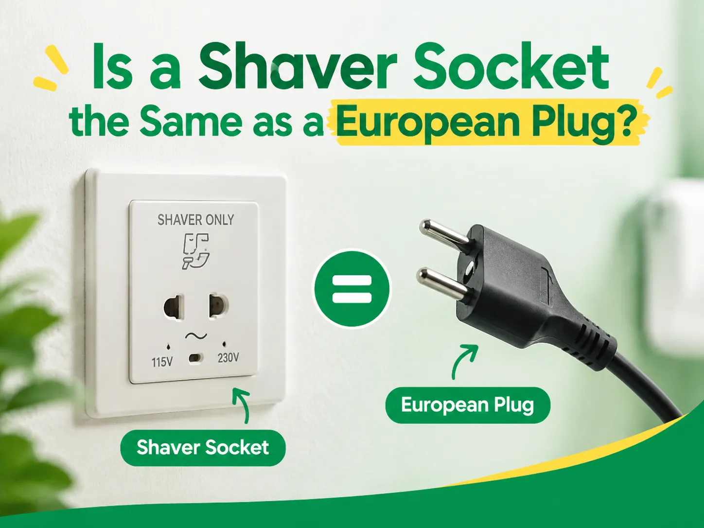
Although they seem to be alike, they both have a round shape with two pins, and they function at a voltage of 230V. This explains why some tourists use a European plug with a British shaver or wonder why a shaver cannot be plugged into a Schuko socket in a Spanish hotel. In reality, they […]

 No.6 Tuozhan Road, Leshang Pioneer Park,Yueqingwan Bay Harbor,Yueqing city,Zhejiang Province


