

Twelve-gauge wire and twenty-amp circuits go together so well that the questions generally arise from a different source. It may be the case that the installer has a piece of 12/3 left over from an earlier wiring project or perhaps the supplier only has 12/3 cables in stock. The question comes up as to whether the presence of an extra conductor has any consequences for domestic wiring. The answer appears simple yet raises some code issues which affect the use of wires, including the small conductor limitations in the National Electrical Code, the way in which twelve-gauge wire can carry twenty amps before problems with voltage drop arise, what advantages can be offered by an additional conductor, and what can take place if a conductor is found to be undersized. The following guide discusses all these aspects as well as installation requirements for receptacles.
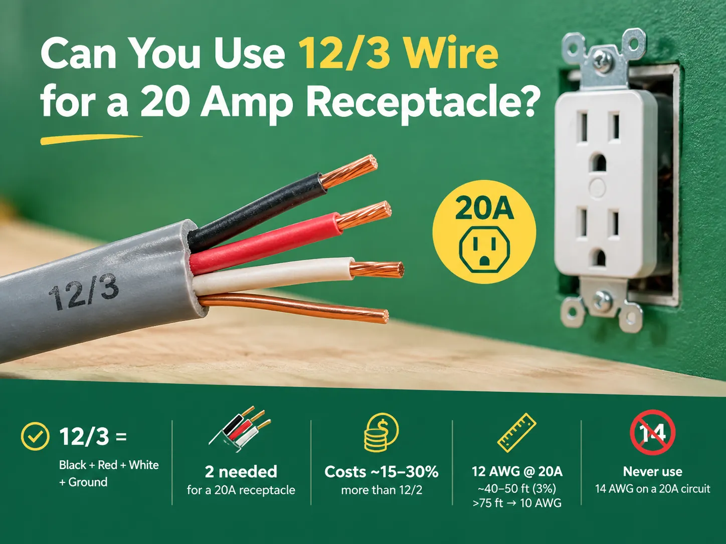
Short response: Indeed, 12/3 copper wire is suitable for a 20 A receptacle circuit and corresponds to the minimum required wire size in National Electrical Code (NEC) mentioned in Article 240.4(D). The “3” indicates that the cable has three insulated wires, i.e., black, red, and white, plus one bare equipment ground wire. Thus, you only need a black and a white wire in a regular 20 A circuit, with the red one being left unused or used in a branch circuit. A 12/3 wire is expected to be 15-30% more expensive than 12/2, and the other wire affects box fill calculations. As for voltage drop, 12 AWG works well at 20 A up to around 40-50 feet. After roughly 75 feet, the voltage drop will exceed 3% specified by the NEC for circuitry, and 10 AWG should be used.
The method of naming electric cables is simple since it only takes two digits, which are both significant.
The first digit indicates the wire gauge using the American Wire Gauge System. For instance; a wire gauge of 12 AWG is a 2.05 mm wide copper wire. The second digit signifies how many conductors are there in the wire. In the example of wire name 12/3 meaning there are three insulated conductors in total. In the case of 12/3 NM-B cable the three conductors are black, red, and white insulated. There is also the fourth wire which is the bare wire.
Thus, 12/3 is not a unique product; rather it represents a simple twelve gauge wire. Hence the wire type of 12/2 in its meaning and qualities. In America colors of wires determine their role; black and red wires are the wires under the electrical pressure, the white wire is the wire which does not pass any current, while the bare one is used to connect all devices into a required circuit. The conventions that apply to the devices these conductors feed are covered in our overview of the different kinds of switches used in electrical installations, and the same logic runs through receptacle wiring.
In the situation of creating the circuit for a standard 20 A electric device there has to be one hot wire, a neutral wire and the bare effective ground. Therefore, there can be applied a 12/2 wire and the fourth one is not needed at all; however, the question arises if the surplus wire may affect the work of the cable.

The guidelines are concise and clear.
Overcurrent limitations for small conductors. Article 240.4(D) of the National Electric Code (NEC) caps overcurrent protection for small conductors, limiting usage of 14 AWG to 15 amps, 12 AWG to 20 amps, and 10 AWG to 30 amps. Thus, due to the limited ability to eliminate heat during its operations, 12 AWG becomes the recommended wire for 20 A circuit while 14 AWG cannot fulfill this role, even though it is practically capable of doing so.
Ampacity. When considering ampacity, it is crucial to consider the type of conductor as well as the temperature rating of insulation and conditions of installation. As far as 12 AWG copper is concerned, one may rely on the value of 20 A specified in association with 60°C and the value of 25 A associated with 75°C. NM-B cable is most commonly considered with reference to the 60°C rating, meaning that 20 A is exactly the value one needs, without any extra margin of safety. However, if the ambient temperature is too high or conductors are bundled together, derating will begin affecting the practical ampacity.
Condictors that are not in use. Nothing forbids the utilization of unused conductors. The only requirement is for such conductors to be safely terminated, avoiding short circuits.
Box fill. In terms of box fill, this is where the need for extra conductor may actually incur some costs. According to Article 314.16 of National Electric Code (NEC), all conductors’ sum must be considered. When incorporating an insulated fourth conductor in a cable run, it needs to be checked that the box would accommodate it.
A conductor that is not in use can be turned to good use if planned carefully, as explained here below.
| Option | How it works | Requirements and caveats |
|---|---|---|
| Cap it and leave it | Terminate the red conductor with a connector at both ends and mark it as unused | Fully compliant; count it for box fill; leave it long enough to identify later |
| Multiwire branch circuit | Black and red supply two separate circuits that share the single white neutral | Requires the two ungrounded conductors on opposite phases and simultaneous disconnection of all conductors at the panel, typically by a two-pole breaker or an approved handle tie; GFCI and AFCI arrangements need care |
| Two receptacles, one cable | Feed the first receptacle on black, daisy-chain to a second position on red, or split a duplex receptacle | Permitted where the box and the device rating allow; a split duplex requires a break-off tab and, in some configurations, a two-pole breaker |
| Three-way or multi-location switching | Use black and red as traveller conductors between switches | A legitimate use of 12/3, though the circuit is a lighting circuit rather than a receptacle circuit |
| 240 V circuit | Black and red as the two ungrounded conductors, ground for safety, white capped | Cannot serve a standard 120 V receptacle; needs a 240 V device or a 240 V load |
Let us look closely at the multi-wire branch circuit because it is the reason behind the purchase of the 12/3 wire. It is a very typical mistake made hence it is worth careful consideration. When two circuits share the same neutral wire, the current through that wire equalizes the two circuits instead of adding them, which only works when the wires are from two different phases. It is important to get this right because otherwise the neutral wire will have to carry the total current from both circuits hence the law requires that in such cases the circuit be disconnected from the supply at once, and use of a two-pole switch is the mainstream practice in such cases. In case the multi-wire circuit supplies power to equipment that should rely on GFCI breakers, it gets much more complex and in fact, many electricians opt not to use that type of circuit in kitchens and bathrooms.
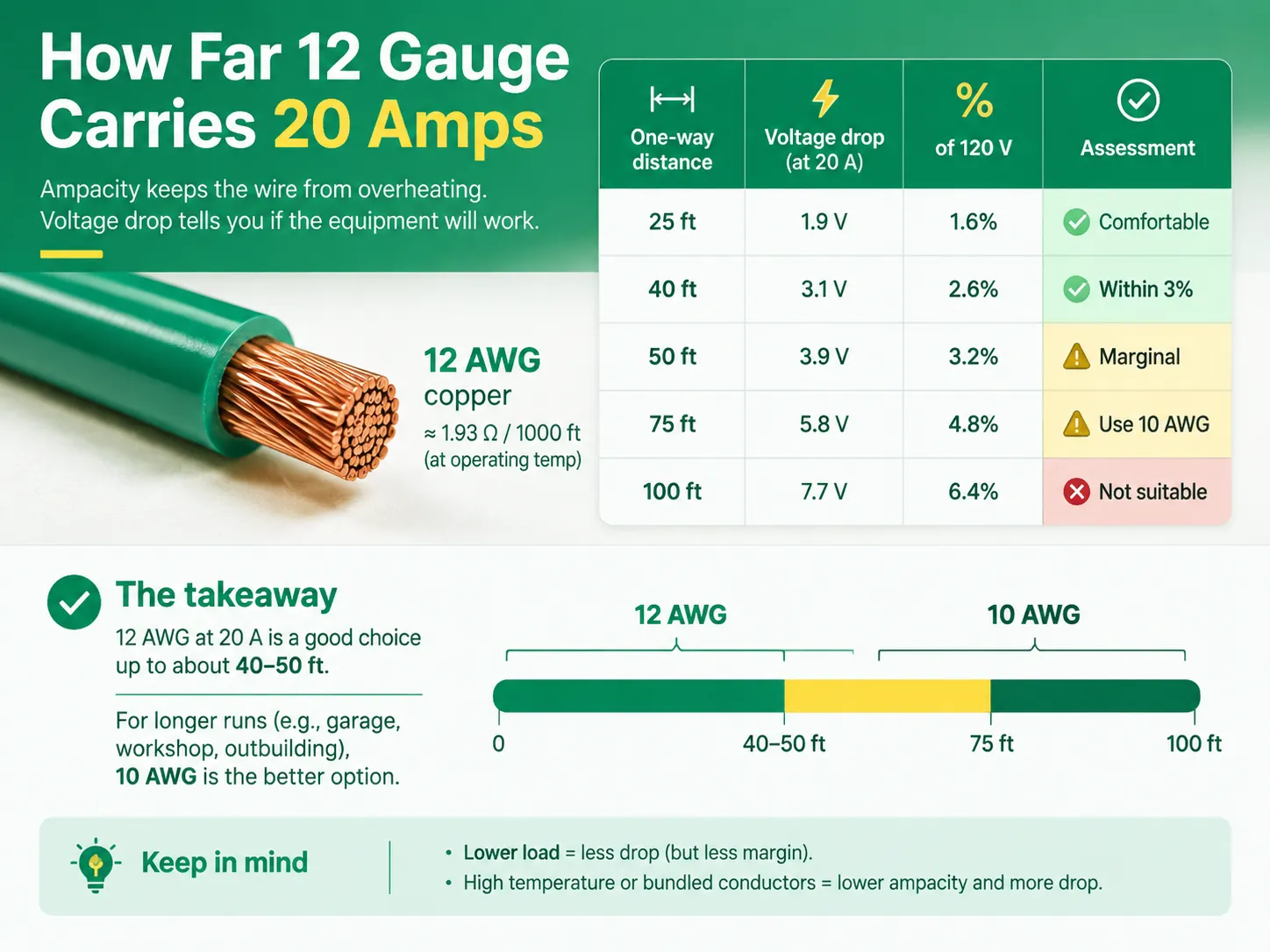
Ampacity indicates whether the wire will overheat, while voltage drop determines whether the equipment on the other end works correctly.
According to the NEC, voltage drop in a branch circuit should not exceed 3%, while the total voltage drop from the service point to the point of use should not exceed 5%. The NEC therefore allows some variance from these values in residential code, but they still exist.
The reason for the above values is that equipment misbehaves due to low voltages. At low voltages, motors run hot, electronics reset, and resistive loads do not perform in the expected manner.
The twelfth gauge copper wire has a resistance of about 1.93 ohms per 1,000 feet at the operating temperature. In 120 volts circuit, the total voltage drop when carrying 20 amps is calculated as presented below.
| One-way distance | Approximate voltage drop at 20 A | Percentage of 120 V | Assessment |
|---|---|---|---|
| 25 ft | 1.9 V | 1.6% | Comfortable |
| 40 ft | 3.1 V | 2.6% | Within the 3% recommendation |
| 50 ft | 3.9 V | 3.2% | Marginally over the recommendation |
| 75 ft | 5.8 V | 4.8% | Too much; step up to 10 AWG |
| 100 ft | 7.7 V | 6.4% | Clearly unsuitable |
On a practical note, 12 AWG cables can handle up to approximately 40-50 feet and 10 AWG is suitable for lengths of about 75 feet or above. Since residential circuits have many receptacles that fall within this distance, the combination is considered standard. Distances in cases of circuits connected to the detached garage or some other outbuilding have to be calculated.
There are two factors involved in the decline in number. The first is that in a circuit that rarely draws the full 20 amps, there is less drop. However, designing on this assumption does not give you any margin for any errors. The other factor involves derating the conductors and the drop that is caused due to the wire’s background temperature or if the envelope has too many wires inside.
Failing in a known way, undersized conductors in a 20 A circuit help bring about the code’s strict insistence on 14 AWG wire.
The popular mistake is to install a bigger fuse to avoid nuisance tripping. However, it can be dangerous because in case of using 12 SWG wire with 20 A circuit connected to a circuit with 30 A fuse, wire will be able to heat up, and it will happen without activating the circuit breaker.
| Cable | Use it for a 20 A receptacle circuit? | When to choose it |
|---|---|---|
| 14/2 | No | 15 A circuits only; prohibited on a 20 A circuit by NEC 240.4(D) |
| 12/2 | Yes — the standard choice | Ordinary 20 A receptacle circuits; cheaper, easier to pull, less box fill |
| 12/3 | Yes | When you need a second ungrounded conductor: multiwire branch circuits, 240 V loads, or traveller conductors |
| 10/2 | Yes — oversized | Long runs where voltage drop exceeds 3%, or high-temperature derating |
| 10/3 | Yes — oversized | 240 V circuits at long distance, or 30 A circuits |
A basic 20 A receptacle circuit likely calls for a 12/2 wire size. While you could use 12/3, this is actually unnecessary since normally there is no use made of the third conductor. If you have some 12/3 leftover, using it does not increase costs in principle apart from some additional box fill and some extra labor to run it through the framing.
When it comes to working with 12 AWG wire, note that the wire is generally stiffer than 14 AWG, as well as it bends more stiffly, leading to the complication of the installation.
The sequence below assumes a conventional daisy-chained receptacle circuit with the cable used in 12/2 fashion. Safe isolation and verification come before anything else, and the general technique — including how to identify conductors when colours are unconventional — is covered in our guide to replacing a light switch, which follows the same discipline.
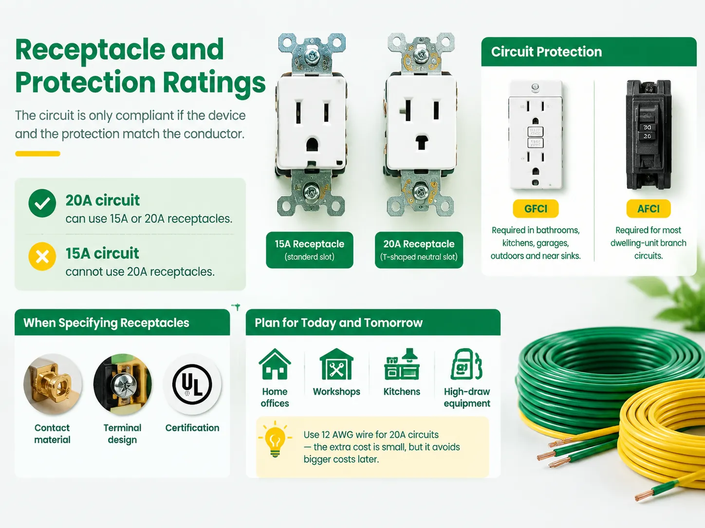
The circuit is only compliant if the gadget and the protection coincide with the conductor.
Receptacle Capacity. A 20 A circuit may have a 15 A receptacle in use. This may surprise some people, but 15 A receptacle is fit for transferring 20 A through to devices relying on it, hence, making it admissible for a 20 A circuit. Conversely, a 20 A receptacle should not be mounted on a 15 A circuit as the latter is not able to provide the power of the device. As to the majority of households, the difference will be seen in face style, which is the way the receptacle looks and in a certain quality of the device, which is better in most cases.
Where receptacles are being specified for a project rather than replaced one at a time, the selection criteria extend to contact material, terminal design, and certification — the same discipline set out in our guide to choosing an electric switch and socket manufacturer.
Capacity is the other half of that decision. Modern receptacle circuits increasingly support more than lamps and vacuum cleaners, and the load profile of the devices plugged into them is changing, as discussed in our article on USB wall outlets and fast charging. Planning the circuit for that reality costs nothing at the wiring stage and a great deal later.
A representative example of how a modern device in this family is documented is our FS328-V dimmer specification, which is the level of detail a specifier should expect before committing a circuit to a device.
One final note for people who install a 20 A circuit: 20 A circuits are being used more often for home offices, workshops, kitchens, or any other location that has a lot of powerful appliances. The cost of using 14 AWG or 12 AWG wire is not much different when considering the cost of opening up a wall later, therefore it might be best to use twelve gauge.
Absolutely. Twelve-gauge copper is a universal wire for any typical 20 A circuit due to it (Secretary Committee (erroneous text: “due to its”), National Electric Code or NEC) being the lowest size acceptable by NEC under the rules for small conductors provided in Article 240.4(D). Standard wire assembly for a 20 A company is a 20 A receptacle using 12 AWG wire and protected with a 20 A breaker. The only requirement is the circuit protection shall follow the convention and must be calibrated at 20 A. This means one cannot install 12 AWG wire and substitute a 30 A breaker for a standard company operation since such actions would disable the protection provided to the wire.
In practice, twelve-gauge copper is the generally accepted wiring solution as well. An alternative solution for 20 A circuits would be ten gauge wire; however, this is only necessary for runs of wire longer than 75 feet where the voltage drop is nonnegligible, or if wire is exposed to high temperature or tightly bundled with other conductors. Fourteen-gauge wire cannot be used in 20 A circuits since according to Article 240.4(D) fourteen AWG wire only limits the performance at 15 A.
When it comes to 20 A current conduction capacity (ampacity), the answer is yes – conducted current is mainly limited by voltage drop rather than the distance. With regard to 20 A of conducted current, 12 AWG copper wires have nearly 3.9 V drop at 50 ft run length and nearly 5.8 V drop at 75 ft run. Therefore, the voltage drop ratio at 20 A of current conduction is approximately 3.2% and 4.8% respectively which allows for the distance of up to 40-50 ft for a 20 A current conduction along 12 AWG wire without any significant voltage drop. In case of longer wire runs it would be better to use ten AWG wire.
Yes, it is possible to install 12/3 wire to a socket as it does not contradict any regulations. One need only close the red wire to both ends in order to utilize it exactly the same way as it is done for 12/2 wires. Another alternative could be a multiwire circuit installation powered by 12/3 cable.
The installation will be highly unsafe, as well as not compliant with any wiring regulations. The thing is that under normal conditions nobody can use fourteen gauge wire for conduction of more than 15 A since Article 240.4(D) of the (wrong phrase: “the”) National Electric Code says that fourteen AWG wire is limited to 15 A. This is why current load will overheat the wire making it unfit for the installation.
For a circuit with a receptacle of 20 A that is made with twelve-three wire, it is permissible as well as reasonable and does not compromise whatsoever. Twelve AWG is the least that the code allows for a 20 A outlet and the extra insulated wire may or may not be used, and compliant capping can be done in two minutes. The important part of making the circuit safe is everything that surrounds the cable: a 20 A circuit being protected with a 20 A circuit breaker, wall socket that corresponds to output rating, GFCI or AFCI protection that is mandated by location, correctly torqued terminations, and run that is short enough for impedance to stay below three percent. If all the above is above board, then the question of whether to use 12/2 or 12/3 depends on convenience and cost rather than compliance.
Twelve-gauge wire and twenty-amp circuits go together so well that the questions generally arise from a different source. It may be the case that the installer has a piece of 12/3 left over from an earlier wiring project or perhaps the supplier only has 12/3 cables in stock. The question comes up as to whether […]

The exceptional situation present in Dubai’s electric appliance sector, which combines British Standard appliances with regulations from a utility as well as a national agency overseeing the implementation of national regulations, necessitates that the appliances be able to endure the high temperatures and humidity experienced in the region because of its coastal location, and also […]

“How many outlets are allowed on a 20 amp circuit?” is one of the most popular questions that people would ask when it comes to doing electrical work at home. Unfortunately, it is also one of the questions that has been most incorrectly answered; most people would give a number based on personal opinion rather […]

 No.6 Tuozhan Road, Leshang Pioneer Park,Yueqingwan Bay Harbor,Yueqing city,Zhejiang Province


