

If you have a long room, hallway, or staircase and want to control one light switch from three different locations which are one at each end of the room and one in the middle. Then you are probably asking one of the most frequently asked and misunderstood questions about home wiring. The answer is surprising: the circuit is not wired using three three-way switches. Instead, when a circuit is controlled from three locations, it requires two 3-way switches at both ends of the circuit and one four-way switch to be connected using the two traveler conductors. This article discusses everything related to the concept, tools, steps involved in wiring, terminals mapping, verification process, and specifications to avoid errors that are mostly made by amateurs.
The response is short: To control one light from three switches you only need two three-way switches and one four-way switch instead of three three-way switches. The first three-way switch gets the hot supply through its common terminal and sends the current out through the two traveler wires. The four-way switch is near the center and switches the travelers at its terminals. The last three-way switch receives the traveler wires and again sends the switched hot to the light. So whenever one switch of the three is turned on, the light is turned off or on irrespective of the position of the other switches. You should switch off the power from the electric breaker, check it with a tester, label every wire properly, and follow the schematics given below.
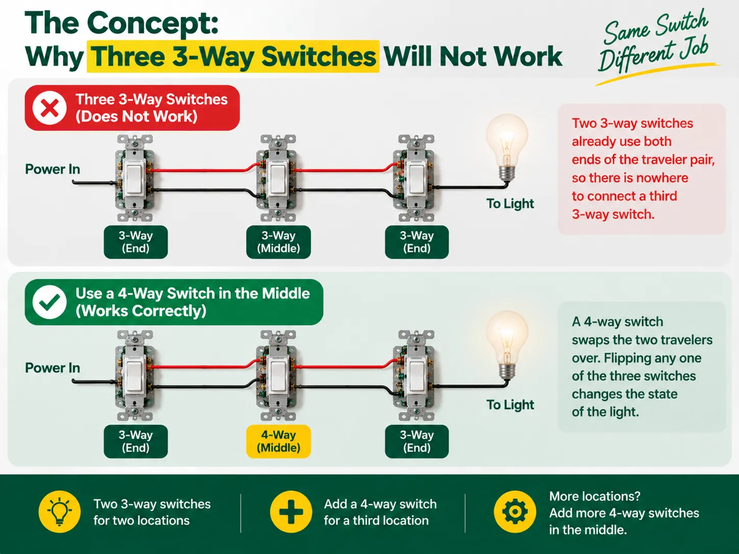
There are no labels that indicate “on” and “off” in 3-way switches as they are not switches in the true sense —they function as a switch that connects two traveler wires. The power is sent to one of the travelers by the first 3-way switch and the other 3-way switch chooses which traveler receives the power and leads to the bulb. Thus the two partners in this process of linking the bulb form a chain, where the switch inputs must match for the bulb to light up, so the light goes off simply by changing the switch.
However, when a third location is added, one tends to see that the traditional system of 3-way switches has already established connection with both ends of the traveler cable, which precludes connecting an additional switch there. What is needed is a totally different device called a 4-way switch, which is mounted between two travelers ready to swap them. With 4-way switch in place, each switch will be able to change the status of the light every time the switch is turned on or off, thus achieving a result desired from three locations. If there is a need for connection of the fourth switch, the number of the devices in place is increased but the principle is the same.
Before starting, it is worth understanding how the whole switch family fits together — the difference between 1-way (single-pole), 2-way (3-way), and intermediate (4-way) designs, and how they are labelled across markets, is explained in our guide to the different kinds of electrical switches.
| Item | Specification |
|---|---|
| 3-way switches × 2 | One for the supply end, one for the light end; both with a “common” terminal plus two traveler terminals |
| 4-way switch × 1 | For the middle location; four terminals (two pairs of travelers) |
| Wire | 14 AWG on a 15 A circuit or 12 AWG on a 20 A circuit (never mix sizes on one circuit) |
| Cable | 14/2 or 12/2 (line, neutral, ground) plus 14/3 or 12/3 between the three boxes for the two travelers plus neutral |
| Boxes and wire connectors | Correct-size junction boxes, wire nuts or lever connectors, electrical tape |
| Tools | Voltage tester (non-contact and multimeter), screwdrivers, wire strippers, needle-nose pliers, flashlight |
The most noteworthy development in recent electrical code updates is a requirement that a neutral cable be included in every switch box so that smart devices can be supported in the future. If possible, use three-cable wiring (which includes the red traveler) and run a neutral cable through all the switch boxes.If your project is replacing old switches rather than new wiring, the box-check and replacement discipline in our light switch replacement guide applies at every location.
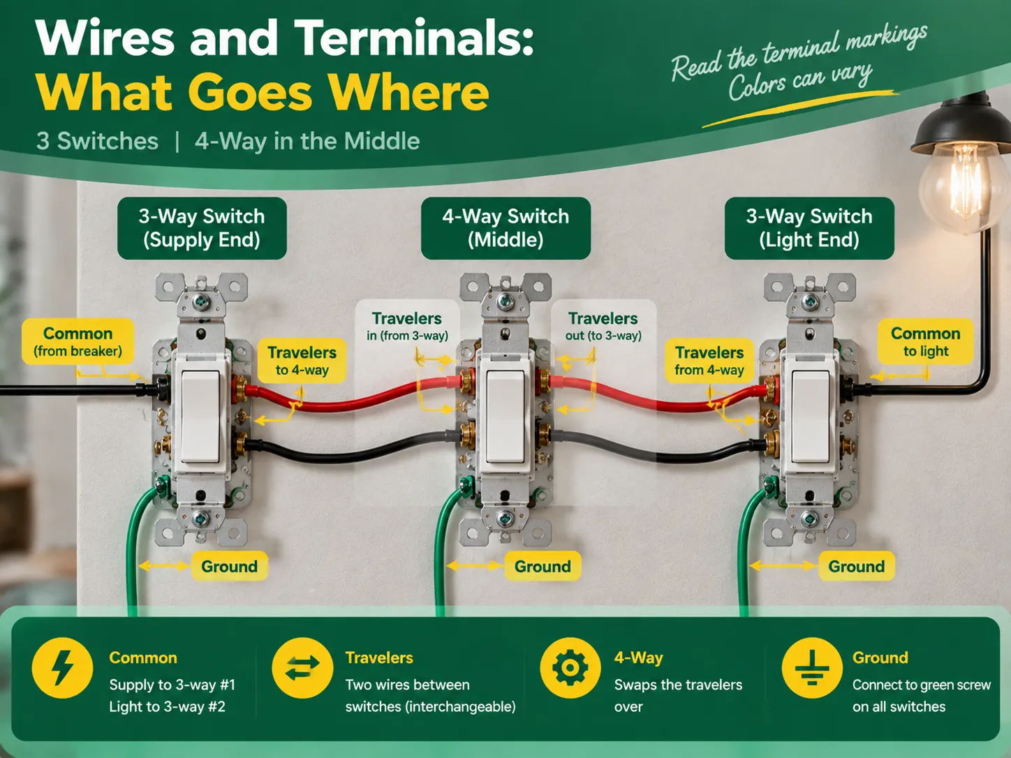
Despite the fact that terminal designations are the same for high-quality switches, colors differ based on the manufacturer, and it is therefore always advisable to check the text on the appliance. Universally accepted role states that:
| Role | Switch | Terminal | What connects |
|---|---|---|---|
| Common (line) | 3-way #1 (supply end) | Darker screw, or marked COMMON / C | The hot supply wire (from the breaker) |
| Travelers | 3-way #1 | Two remaining screws (brass, or marked 1 and 2) | The two traveler wires running to the 4-way |
| Traveler pair in | 4-way (middle) | One pair of terminals | The travelers coming from 3-way #1 |
| Traveler pair out | 4-way | The other pair of terminals | The travelers continuing to 3-way #2 |
| Travelers | 3-way #2 (light end) | Two traveler screws | The travelers coming from the 4-way |
| Common (load) | 3-way #2 | Common terminal | The switched wire running to the light |
The two traveler wires should preferably be colored the same (for example, the black wire and red wire in cable 14/3 for the US or two identical wires in the three-core-and-earth UK cable). In this case, it is good news to know that travelers may be changes without any concerns, provided that they remain unchanged when passing the 4-way switch. However, the common terminal is not interchangeable.
Act with deliberation, one compartment at a time, and treat every wire as hot until you eliminate the doubt.
The verification comes in three steps during which the two common wiring mistakes can be identified – incorrect wiring and crossed traveler continuity.
Almost all unsuccessful three-switch circuits can be attributed to one of the following errors:
Almost none of the aforementioned mistakes can escape being revealed during continuity check; hence “the checking part” is so important.
No, you will never have three 3-way switches in one circuit. You need two 3-way switches to control one light via three power sources, plus one 4-way switch in the middle. To add more than three switches to control the light, you will add another 4-way switch between the 3-way switches.
There are five most practial mistakes: using three 3-way switches instead of two 3-way and one 4-way switch, incorrectly connecting the power source to the traveler terminal instead of the common terminal, switching the neutral instead of connecting it through the wires, incorrectly connecting the travelers in the 4-way switch, and skipping the grounding and labelling of the wires. All these mistakes can be detected by a continuity test before turning the power on.
The 3-way switch has one dark marked terminal (the common terminal) to which the wire from the hot supply at one end and wire from the light at that end of the circuit should be connected. The two brass traveler terminals are to take two wires connecting the 3-way switch with the 4-way one. In the 4-way switch, one pair of traveler wires is to be connected to one pair of terminals.
If these three lights are to be switched on/off simultaneously from all three locations, then the multi-way circuit needs to be made in the same way but the lights have to be connected in parallel from the load-end common terminal. If each of the switches from each location is to control its own light, it is not a multi-way but three independent circuits.
The process of wiring a single light to three switches is an interesting illustration of how understanding the basics leads to effective electrical project completion. In this case, the key concept is the fact that a multiway circuit consists of two 3-way “selector” switches and one or more 4-way “mutator” switches in between. To create a three-way circuit one simply requires two 3-way switches and a 4-way switch wired in a way so that the line feeds the common terminal of the first 3-way switch, travelers run through the 4-way switch, and the common terminal of the last 3-way switch leads to the light. To complete the wiring project correctly, one must do the following: follow the terminal configuration mapping, wire the neutrals straight passing through all boxes, ground components as needed, mark the load and line terminals, and look up for a continuity check on the circuit after its completion. It is also important to remember that only quality switches should be used in the project and that the best switches come from reliable manufacturers. This specific aspect of the process is discussed in detail in the articles on the choice of an electrical switch and socket manufacturer since all the techniques used to check the quality of electrical switches and connectors are the ones used in the manufacturing process of electrical devices.
If you have a long room, hallway, or staircase and want to control one light switch from three different locations which are one at each end of the room and one in the middle. Then you are probably asking one of the most frequently asked and misunderstood questions about home wiring. The answer is surprising: […]

The district of Greenwich offers a unique combination of historical importance and modernity, which can be seen in its historical sites as well as its contemporary apartment buildings. In Greenwich, the old and the modern coexist in harmony. Despite the presence of the antique buildings of the Georgian architecture, they can be installed with the […]

If you know the two round-pin rules, you will find Spain is one of the simplest places in Europe to keep your devices charged and connected, as countries across the mainland have the same plug sockets. Those travelling to Spain from the UK, USA, and Asia require just a single adaptor. This article explains all […]

 No.6 Tuozhan Road, Leshang Pioneer Park,Yueqingwan Bay Harbor,Yueqing city,Zhejiang Province


