

So, you just got yourself a cool new dimmer switch and you’re staring at the wall plate in your living room, pondering whether you can do the installation yourself or whether you must call an electrician. You’re motivated to dim your dining chandelier while having guests over for dinner, lower the bathroom lights while getting ready for bed, or cut your energy usage by about 20-30% throughout the entire house. Whatever your reason may be, installing a dimmer switch is a great and affordable electrical job you can do yourself. In this guide, you will learn how to do this correctly by following these steps: selecting a suitable dimmer, turning off the power before starting your work, taking off the old wall plate, understanding what each wire reduces, connecting the wires properly, installation of the new device, and testing our invention. You will also discover some common problems that can make your dimmer malfunction, so you can avoid them.
Quick answer: Yes, it’s possible to install a dimmer switch on your own as long as you have a single-pole switch (one switch controls a single light), some basic tools (a voltage tester, screwdriver and wire strippers) as well as just 15 to 30 minutes. If your installation involves 3-way switches (two switches controlling one light), non-neutral wiring, or aluminum wiring, it’s better to call a qualified electrician. And remember to check if your light bulb is dimmable and the wattage is adequate.
Not each and every dimmer switch is alike. Prior to beginning your installation, it is essential to ensure that the dimmer you select matches with your lighting arrangement. Incorrect choice is the most common cause causing buzzing and flickering of dimmer switches.
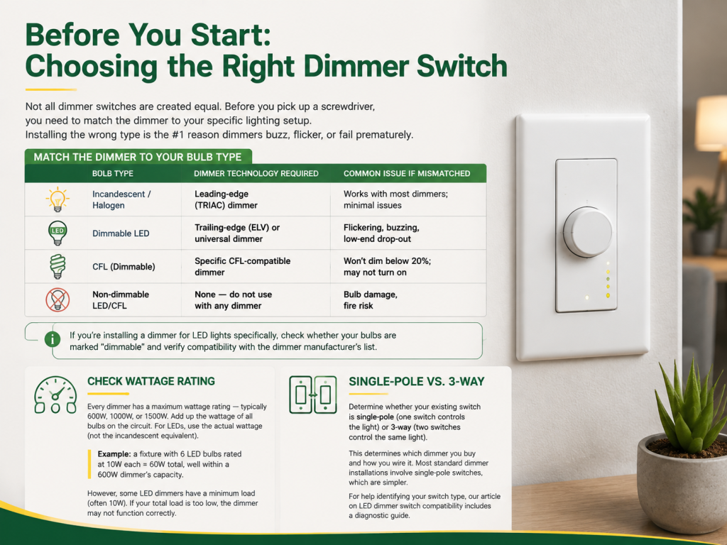
The technology of a dimmer certainly needs to work with the light bulbs that are being used in the light fixture; in case of using mismatched components, issues such as flickering, decreased lifespan of the light bulb, or total failure can occur.
| Bulb Type | Dimmer Technology Required | Common Issue If Mismatched |
|---|---|---|
| Incandescent / Halogen | Leading-edge (TRIAC) dimmer | Works with most dimmers; minimal issues |
| Dimmable LED | Trailing-edge (ELV) or universal dimmer | Flickering, buzzing, low-end drop-out |
| CFL (Dimmable) | Specific CFL-compatible dimmer | Won’t dim below 20%; may not turn on |
| Non-dimmable LED/CFL | None — do not use with any dimmer | Bulb damage, fire risk |
In case you are going to use a dimmer for LED lamps, make sure you have checked whether your lamps have “dimmable” tag and have compared it with the lists of the manufacturers to see whether the products are compatible.
All dimmer switches are rated in wattage such as 600W, 1000W, or 1500W. To find out how much wattage you are using on a circuit with bulbs, you need to add up the wattage of all bulbs. In the case of LED bulbs, it’s necessary to consider their actual wattage (not incandescent equivalent) in calculations. For example, 6 LED bulbs rated at 10watts each give a total wattage used in the circuit of 60W, which means it’s safe to use them on a 600W dimmer switch. On the other hand, some LED dimmers may have minimum load requirements (in most cases, it’s around 10W) and if your load is lower than that, the dimmer won’t work correctly.
Figure out if your current light switch setup involves a single pole (a single switch controls the light) or a three way switch (two switches control the same light). This is key in determining what style dimmer to buy and how to wire it. Most dimmers are installed with ease of compatibility with single pole.
Having the right tools ready before you start prevents mid-project trips to the hardware store. Here’s your checklist:
| Tool / Material | Purpose | Required? |
|---|---|---|
| Voltage tester (non-contact or probe) | Verify power is off before touching wires | Essential — do not skip |
| Phillips and flathead screwdrivers | Remove switch plate, disconnect wires, mount new dimmer | Essential |
| Wire strippers / pliers | Strip insulation, bend wire ends, twist wire nuts | Essential |
| Wire nuts (provided with dimmer) | Connect dimmer wires to house wiring | Essential (usually included) |
| Electrical tape (optional) | Wrap wire nuts for extra security | Recommended |
| Flashlight or headlamp | See inside the electrical box | Recommended |
| Wire labels or masking tape | Label wires before disconnecting | Recommended (especially for 3-way) |
| New dimmer switch | The actual product you’re installing | Essential |
| New wall plate (if size differs) | Cover the dimmer cleanly | If needed |
For the dimmer switch itself, ensure it’s UL-listed and rated for your application.
This step is very important in the whole process. Don’t ever touch an electrical switch with power on. Even the most experienced electricians abide by this rule without exception.
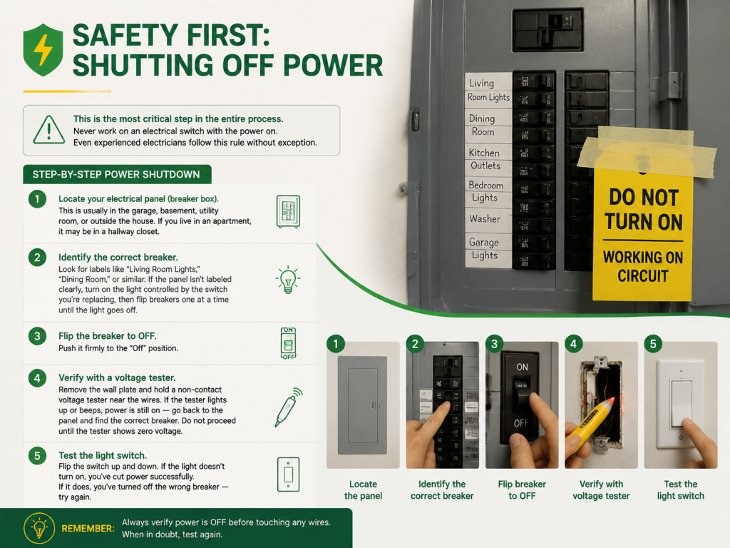
Electricians may place caution tape over the breaker that states “DO NOT TURN ON – WORKING ON CIRCUIT.” This is a warning that no one else should alter the switch positions without permission.
⚠ Warning: Make sure to use a voltage tester before handling any wire, even when the circuit breaker is off. Some houses that are quite older still have shared neutrals and multiwire branch connections that can cause voltage to backfeed into what is believed to be a dead circuit. If your voltage tester detects any voltage, stop working and contact an expert electrician right away.
With power confirmed off, you’re ready to physically remove the existing switch.
Having taken away the mentioned wires, you can dispose of your old switch. You should have 2 to 4 wires coming out of the box: usually, either two wires of the same color or two wires of a different color.
Correctly identifying each wire’s function is the difference between a working dimmer and a short circuit. Here’s how to tell them apart:
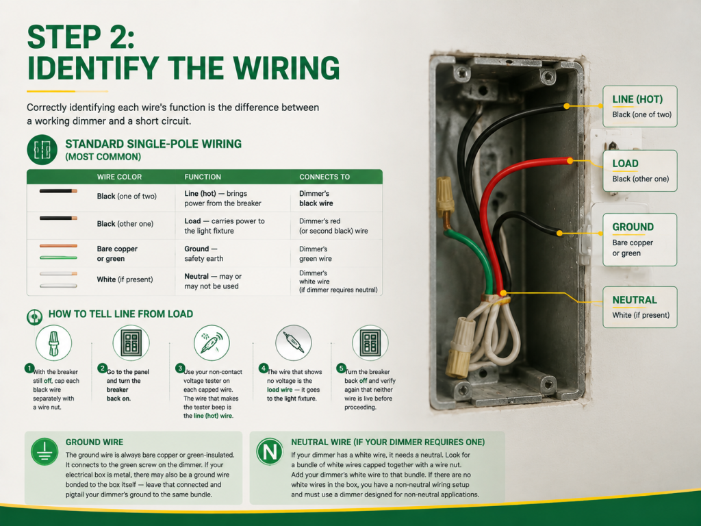
| Wire Color | Function | Connects To |
|---|---|---|
| Black (one of two) | Line (hot) — brings power from the breaker | Dimmer’s black wire |
| Black (other one) | Load — carries power to the light fixture | Dimmer’s red (or second black) wire |
| Bare copper or green | Ground — safety earth | Dimmer’s green wire |
| White (if present) | Neutral — may or may not be used | Dimmer’s white wire (if dimmer requires neutral) |
In the case of the single-pole switch, both the black wires seem to be alike.
In case you are unsure of which wire is which or feel uneasy about that step, label both wires and seek assistance from an electrician since you cannot afford to guess.
The ground wire is always bare copper or green-insulated. It connects to the green screw on the dimmer. If your electrical box is metal, there may also be a ground wire bonded to the box itself — leave that connected and pigtail your dimmer’s ground to the same bundle.
Certain types of today’s dimmers, particularly the smart ones, require a neutral wire. If your dimmer features a white wire, it will necessarily require a neutral. In your switch box, check if there are wires bundled with a wire nut. If that’s the case, connect your dimmer’s white wire to them, but if those wires are absent, you’ll have to use a dimmer that doesn’t require a neutral wire.
Now comes the actual connection. Take your time — a loose wire nut is the most common cause of dimmer failure.
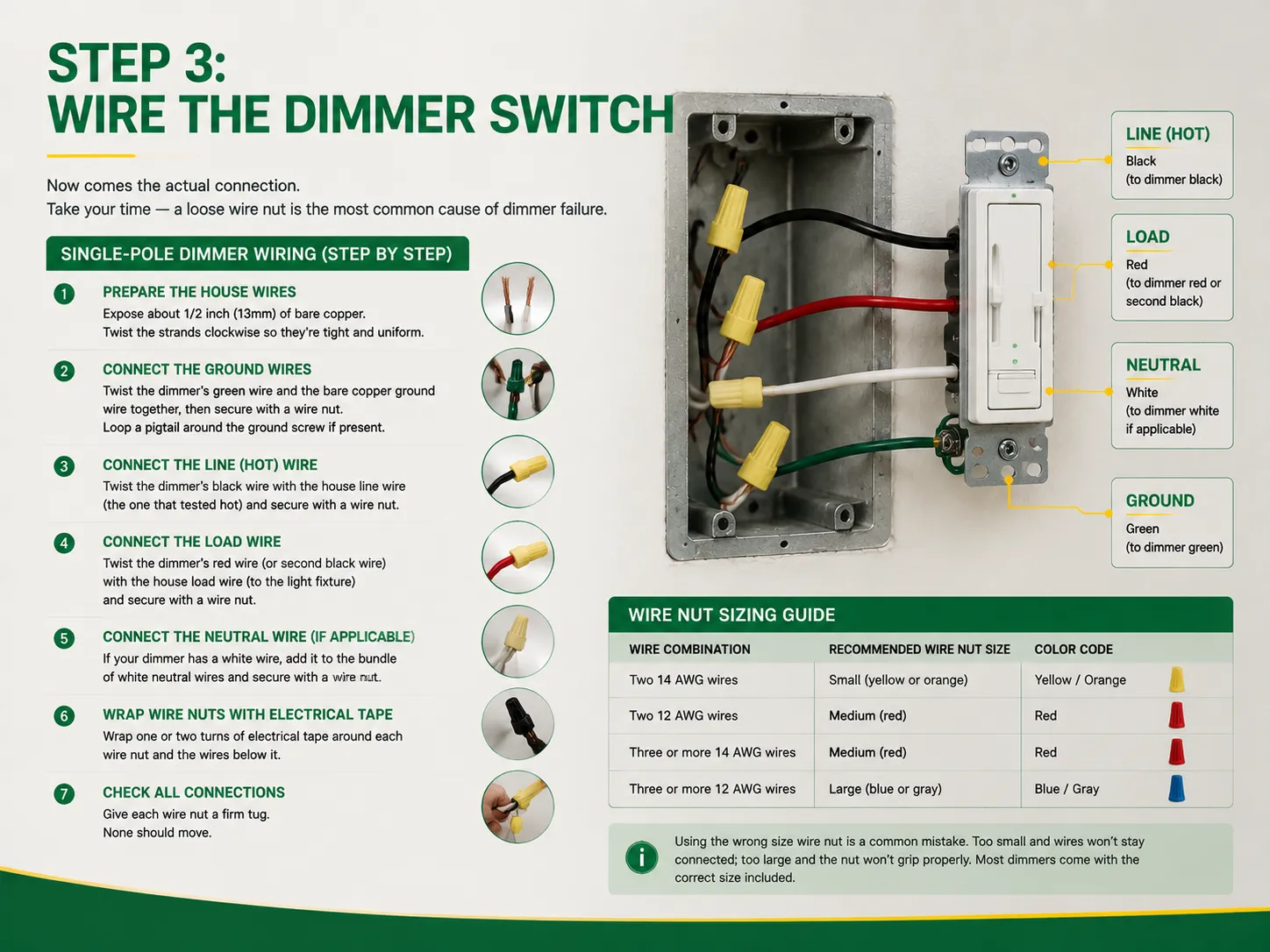
If you are using a standard dimmer, it will have 3 pre-terminated wire leads for connection: the black wire, the red wire (or second black), and the green wire. The following procedure explains how to connect them:
| Wire Combination | Recommended Wire Nut Size | Color Code |
|---|---|---|
| Two 14 AWG wires | Small (yellow or orange) | Yellow / Orange |
| Two 12 AWG wires | Medium (red) | Red |
| Three or more 14 AWG wires | Medium (red) | Red |
| Three or more 12 AWG wires | Large (blue or gray) | Blue / Gray |
Another popular mistake is choosing the wrong size wire nut. A small nut will not hold the wires together, whereas an oversized nut will not keep them together well. Most dimmers will usually come with the right size.
You’re in the home stretch. Here’s how to finish cleanly and safely.
If the light fixture is not working at all, the possible explanation is that the line and load connections are inverted. Turn OFF the circuit breaker, fix the wires and check the dimmer again.
The 3-way switch system uses two switches to control the same light (for example, one switch at the top and another at the bottom of a flight of stairs). The installation of a dimmer would be a bit tricky but achievable if you know what you’re doing.
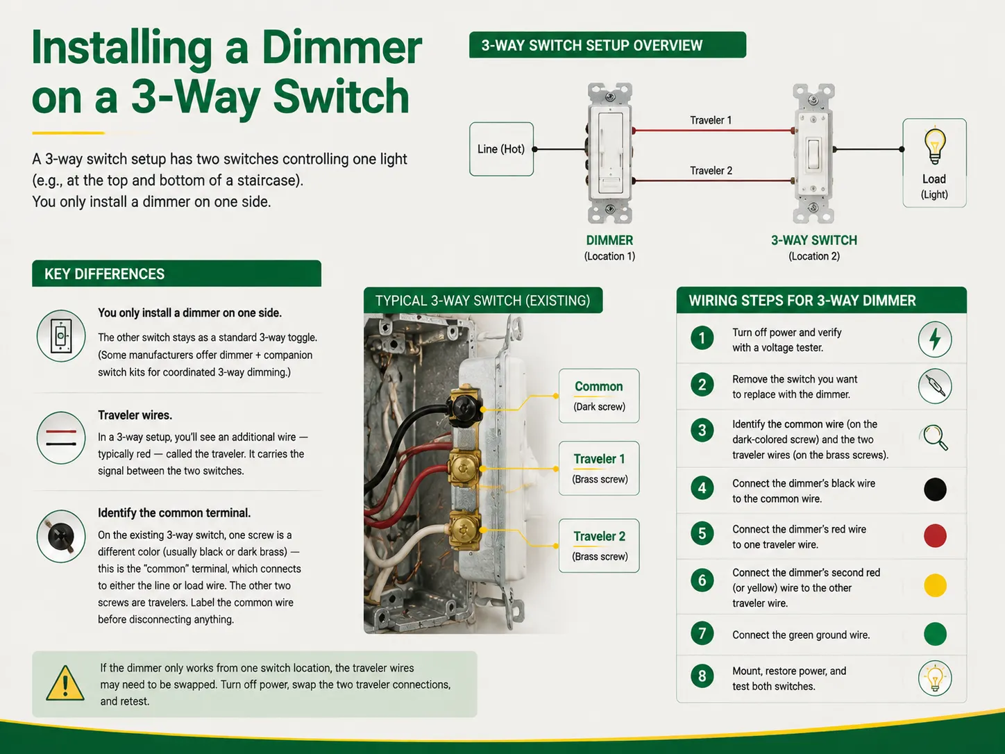
If the dimmer works from one switch location only, swapping the traveler wires is required. To do this, turn off the power, switch the two traveler wires and test the dimmer in use again.
Even with precise installation, problems can occur. Here are the most prevalent issues along with their solutions:
Reasons: The bulb is not dimmable or the dimmer is incompatible with its type. Especially, LEDs are sensitive in case of dimmer technology mismatch.
The Solution: Ensure the bulb is “dimmable.” Check the package of the dimmer to see if it is compatible with LED and minimum load “requirements.” Replace the whole bulbs with dimmable LED ones if non-dimmable ones are in use.
Reason: The dimmer is overloaded (the total wattage is higher than it should be) or it is a bad quality dimmer and it does not filter well.
The Solution: Calculate the wattage of the bulbs. If it exceeds 80 % of the power of the dimmer (for example, 480 W for 600 W dimmer), then buy a better dimmer. Although it is normal to hear a weak hum, loud buzzing should not be audible.
Reason: Ground fault (ground wire touches the hot wire), short circuit (line and load wires touch each other); an overloaded circuit may also cause the problem.
The Solution: Switch off the power supply and check every all the wires and the positions of the wire nuts, ensuring they do not touch.
Reason: The line and load wires are in the wrong terminals or the switch inside the dimmer is faulty.
The Solution: Turn off the power, change the line and load connections in the dimmer and turn on again.
Reason: There are no neutral wires connected, the dimmer is out of the range of Wi-Fi or the hub cannot work with the smart dimmer.
The Solution: Make sure that there are neutral wires in the dimmer. Bring the router closer. Ensure that the dimmer is compatible with the hub.
DIY dimmer installation is safe for most single-pole, standard-wiring scenarios. However, some situations require professional expertise:
| Situation | Why It’s Risky | Action |
|---|---|---|
| Aluminum wiring (common in homes built 1965–1973) | Aluminum expands/contracts differently than copper; connections loosen over time and cause fire hazards | Hire a licensed electrician |
| No ground wire in the box | Dimmer requires ground for safe operation; without it, metal parts can become energized | Have an electrician run a ground wire or install a GFCI-protected circuit |
| Knob-and-tube wiring (pre-1940s homes) | No ground, old insulation may be brittle, fire risk is high | Do not attempt; call an electrician |
| Multiple switches share one box (multi-gang) | Tight space, complex wiring, higher risk of crossing circuits | Proceed only if experienced; otherwise hire a pro |
| Dimmer feels hot after installation | May indicate overloading or poor connection | Turn off breaker and call an electrician |
| Uncertain about wire identification | Wrong connection = short circuit or fire | When in doubt, call a professional |
The average charge of a certified electrician for a standard dimmer installation is said to be between $75 and $200. This is a trifling price in comparison to the price of an electrical fire. If in doubt or unsure, call a licensed electrician for assistance.
Yes, the installation of a dimmer switch can be carried out by most homeowners with a basic understanding of electrical work, provided the switch is a standard simple 1-pole dimmer with copper wires and a ground wire connected. It takes only 15 to 30 minutes to complete the job, and the required tools are simple too, proper tools are a voltmeter, screwdriver, wire strippers, and wire nuts. You also need to ensure that you switch off the relevant breaker and confirm with the voltmeter that the wires do not carry any current before you start working with them. However, in the event of the use of aluminum wires before, a 3-way circuit system that does not have a clear labeling of wires, or with knob-and-tube wiring, or if there is any sort of doubt regarding identifying different wires, it is better to call a licensed electrician.
A dimmer switch can function properly only when it is used with bulbs that can be dimmed. Incandescent and halogen light bulbs can always be dimmed. The LED light bulbs that can be dimmed should have a dimmable label on the pack while non-dimmable LED light bulbs can cause flickering and damage if used with a dimmer switch. It is also important to ensure that the dimmer rating is higher than the total power of every light bulb in the circuit. It is also important to make sure that one can use the dimmer switch with a particular light fixture as sometimes specific dimmer switches are needed.
If you are replacing a standard copper wire, single pole switch, calling your electrician may not be necessary. Because the possibilities are countless, it is wise to hire a certified electrician if: You have aluminum wiring (houses built between 1965 and 1973), knob-and-tube wiring (a method used prior to the 1940s), you do not see a ground wire in the box, you have a 3-way switch, which you are not sure how to label, you do not feel comfortable with multi-gang boxes containing more than one switch, or simply when you do not know which wire is which. Generally, professionals charge approximately $75 to $200. However, you should see that the money spent on professional services is considerably lower than the potential cost of an electric fire.
When working with a standard single pole dimmer, there are three wire connections you need to make: (1) the black wire of the dimmer to the power line/hot wire of the house; (2) the red wire of the dimmer (or second black wire to the load wire of the house; and (3) green wire to the bare copper ground. Use wire nuts to secure all the connections made and check each one with pencil test. If the dimmer has a white wire, connect it to the wires of the same color from the box. For 3-way dimmer, connect the black wire to the common terminal and the red and traveler wire to the traveler terminals. Always make sure that the breaker is turned off before working with the current.
Installing a dimmer switch is an effective DIY project that is extremely gratifying. The efforts are quickly rewarded with lower electricity bills, improved atmosphere, and longer light bulb life. Overall, installation of dimmer switches consist of four simple phases – turn off the current and make sure of that with a voltage tester, extract the old switch and note the wires position, connect according to the colors and types of the wire with the use of wire nuts, and install the dimmer switch, restore the electricity and test it. The whole process usually takes 15-30 minutes if the project is aimed at changing a single-pole switch.
Two things that distinguish successful installation from dangerous one are power safety (always verify whether the breaker switch is off with the help of a voltage tester before touching wires) and proper wire identification (correct line-wires differentiation). In case of correct understanding of the process, usage of necessary and correctly sized nuts, the dimmer switch will work successfully for years. If during the installation the electrician notices aluminum wires, absence of grounding wire, complicated 3-way system, or any differences from the installation manual, it means the process should be stopped and a qualified electrician should be called upon. The fee for the electrician will be relatively low compared to the troubles he will help to avoid.
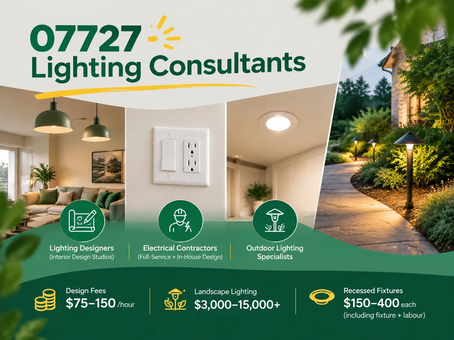
Farmingdale, along with parts of Wall Township and Tinton Falls, New Jersey, share the same zip code of 07727. Most of the houses built from the 1950s to the 1990s still exist today. Most of the homeowners are renovating their houses as opposed to building new homes. Homeowners tend to spend a lot more on […]

The term “07984 lighting consultants” gives people the impression that the five digits represent a postal code of some sort that indicates the place where lighting consultants provide services. This is, however, incorrect: there is no postal area coded 07984, which is only a code of mobile telecommunications in Great Britain. This means that the […]

San Francisco is not the average lighting control market. The housing stock is old and dense, and the electrical code does not allow for as many electrical installations as is allowed almost anywhere else in the U.S. Most homes that want complex lighting are Victorian or Edwardian buildings where no one wants to start opening […]

 No.6 Tuozhan Road, Leshang Pioneer Park,Yueqingwan Bay Harbor,Yueqing city,Zhejiang Province


