

In 2025, the global industrial electrification market was estimated to be worth $47.55 billion. By 2034 it reaches $95.79 billion at an 8.10% CAGR. The boundary-crossing nature of electrical projects is making the symbol standard used in technical documentation more than just a drafting preference. This is one of the procurement and project risks that can impact the installation process.
In this guide, you will learn:
Two standards. One electrical reality. The same components, voltages, currents and switching functions are defined in both the ANSI and IEC standards. The difference lies in the pictorial system that can be employed for their representation and in the geographic context in which each language will be demanded.
ANSI was an outgrowth of American engineering practice in the mid 20th century and has been codified in IEEE 315. The International Electrotechnical Commission (IEC) adopted the standard throughout Europe, Asia, Australia, as well as most of the world outside North America.
The practical consequence is straightforward. An engineer trained in Germany reads IEC electrical schematic symbols naturally and may struggle with ANSI documentation without a reference guide. If a U.S. engineer is reading European or Asian project drawings, he/she is in the same position. There is no technical superiority of either standard. It’s only a matter of custom and the history of regional adoption.
Knowing both is essential for anyone who wants to buy electrical products or run projects in several countries. It’s a minimum requirement.
The visual differences are consistent, and can be easily identified once you know what to look for.
The resistor is the most obvious application. In ANSI notation it is shown as a zigzag line, which is based on the physical form that was used in the early days of resistance wire. The same component is represented as a simple rectangle in IEC notation. A completely different visual form, the same electrical function.
The same holds true for switches. ANSI switch symbols are more likely to employ more representational forms indicating the physical mechanism for opening and closing. Symbols used in IEC are predominantly geometric and of uniform angles and line weights.
The ground symbols are also different. In numerous configurations, the filled triangle pointed down is used by the ANSI. IEC uses a series of horizontal lines of decreasing length. The presence of multiple ground references on a complex schematic can cause the connections to be made incorrectly, which won’t be apparent at installation time.
Symbols for relays vary in a number of important respects for control circuit documentation. ANSI represents the coil as a circle. IEC represents it as a rectangle. A drawing that contains a dozen or so relay references, including a mix of conventions, will cause real confusion to the technician who is using it in the field.
The majority of electrical CAD software now provides for symbol libraries at the project level. However, the knowledge of the meaning of each symbol used in each of the systems is still needed for anyone who has to review or approve documentation manually.
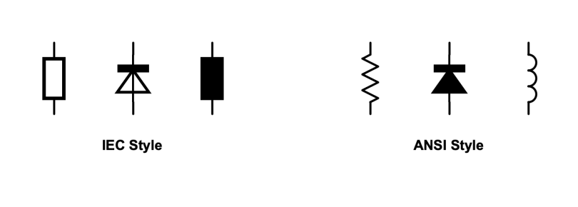
The coding systems employed with the symbols are as much variant as the visual forms.
ANSI employs a device number system for application primarily in protective relay and power system applications. These are number designations that are fixed to functions. ANSI device number 50 is an instantaneous overcurrent protection device. When the device number is 87, it indicates differential protection. These numbers are a technical language taught to engineers in North American power systems in addition to the schematic symbol.
IEC uses a function-based alphanumeric coding system instead. Different components have different codes indicating their function in the circuit. K1 is used to identify a contactor or relay used in the switching function. A main disconnecting device is designated as Q1. The code expresses its function before it knows anything about the shape of the component.
In practical terms, projects that cross standards require specific symbol legends as a guide at the beginning of each document set. The legend will translate the one system’s designations to the other, avoiding misinterpretation in design review, procurement and installation.
There is a well-established geographic split and it is consistent.
North America defaults to ANSI electrical symbols. ANSIs are routinely created and read by utilities, industrial facilities and electrical contractors throughout the United States and Canada. No matter how much international harmonisation is effected overnight, that is not realistic.
IEC is used in most of Latin America, Africa, Asia and Europe. In these areas, engineers might not have to deal with ANSI documentation in their career at all, unless they are working on cross-boundary projects or with North American clients.
The division poses a problem for OEM manufacturers and export-oriented distributors in terms of documentation. Having parallel sets of technical documentation in North America and Europe for the same product can be an issue. IEC markets are not included in the production of only ANSI documentation and vice versa. Global operations will always have both or be based on engineering software that can create both.
Now, that’s where your standard documentation comes into play and can directly impact your market reach.
Yes, but, it’s relevant only to the local area, not the world.
ANSI is still the standard across North America, in both the utilities and industrial sectors and with electrical contractors. It isn’t going away. But outside North America, IEC has won. The short answer is that ANSI is not a global standard; it is a regional standard.
That’s where knowledge has its practical impact on procurement teams.
Errors in wiring that occur while installing are costly and sometimes hazardous when there are schematic symbol misreadings. An IEC ground symbol, read as an ANSI signal reference, is an incorrect connection. This error doesn’t always appear when a database is being commissioned.
The project risk arises from the standard mismatch in multi-country installations. Explicit translations are needed when there is a control panel that was made according to ANSI and installed by a team trained to IEC documentation. That translation process brings with it real risk in the form of delay, review cost, and error probability, which competent project managers budget.
Multi-market projects require documentation of products in both systems. Product certification must comply with the installation standards of the desired country. A procurement gap that arises during the inspection/approval process and not before is the sourcing of electrical products without conducting verification to ensure that the product is of a standard that is compatible with the project’s documentation system.
For distributors and procurement teams managing projects across ANSI and IEC markets simultaneously, the product range needs to cover both sides of that divide without requiring entirely separate supply relationships for each region.
IGOTO Electric covers EU, AU, US, and VN standards within one product range. CE and CB certifications ensure legal market access across countries with different regulatory frameworks, which simplifies the compliance documentation that multi-market projects require. The range includes grounded sockets, USB-integrated variants, and configurations addressing the specific installation requirements of different regional markets rather than a single universal format that fits none of them precisely.
For distributors building inventory across ANSI and IEC market territories, sourcing from a manufacturer whose certifications already span both regulatory environments removes one layer of procurement complexity from an already complex process.
Learn more about IGOTO’s internationally certified product range at igotoele.com.

Farmingdale, along with parts of Wall Township and Tinton Falls, New Jersey, share the same zip code of 07727. Most of the houses built from the 1950s to the 1990s still exist today. Most of the homeowners are renovating their houses as opposed to building new homes. Homeowners tend to spend a lot more on […]

The term “07984 lighting consultants” gives people the impression that the five digits represent a postal code of some sort that indicates the place where lighting consultants provide services. This is, however, incorrect: there is no postal area coded 07984, which is only a code of mobile telecommunications in Great Britain. This means that the […]

San Francisco is not the average lighting control market. The housing stock is old and dense, and the electrical code does not allow for as many electrical installations as is allowed almost anywhere else in the U.S. Most homes that want complex lighting are Victorian or Edwardian buildings where no one wants to start opening […]

 No.6 Tuozhan Road, Leshang Pioneer Park,Yueqingwan Bay Harbor,Yueqing city,Zhejiang Province


