

Two types of terminals can define how a GFCI outlet functions: One terminal is for an individual outlet and the other terminal can protect several outlets from a single GFCI outlet at the same cost. Using the appropriate terminal allows you to take advantage of the cost savings of using a single GFCI, while using the incorrect terminal may cause your GFCI to not reset or cause the downstream outlets to appear to be protected when they are not protected. This guide explains how each terminal works, how to verify the source prior to working, potential fault conditions with GFCIs, and what lettering is required by code.
There are essentially two varieties of terminals which dictate how a GFCI is wired. The first terminal supplies power to an individual GFCI and the second terminal enables you to use a single GFCI to provide Ground Fault Circuit Interruption (GFCI) protection for multiple GFCIs from one location allowing you to save on GFCI outlet installations. By wiring the appropriate terminal, you can take full advantage of the per outlet savings offered by using a single GFCI for your downstream GFCIs, while using the incorrect terminal may cause the downstream GFCI’s not to reset or may cause the downstream GFCIs to appear to have GFCI protection when in reality they do not. In this guide, you will learn about the functions of both terminals, how to identify the source of power before performing electrical work, possible fault conditions with GFCIs, as well as the code required lettering for GFCIs.
A GFCI receptacle is unlike any other devices of its kind because instead of being a one-sided device that passes a majority of its current without preemptively checking it, it is a true two-sided device; one side of which receives, while the other one distributes.
The LINE side is represented by the conductors being plugged in from the circuit breaker in the branch circuit. The power that comes in this part is used to feed the electronics of the GFCI itself, as well as its transformer, which it needs, when operating.
As for the LOAD side, it stands for the output side. As such, any standard receptacle, which is being powered by these terminals, receives the current through GFCI’ circuit, which means that the ground fault at the outlet will trip the GFCI like it was tripped before. This is how one GFCI provides protection for several outlets.
Almost everything happening in GFCI is due to this configuration. The internal transformer in this case consists of the toroidal wires, which help to measure the outgoing and incoming current. The flow from LINE to LOAD will be considered; however, if there is something that goes around this current it won’t be considered. The relationship between the device and the circuit it protects is the same one described in this explanation of why circuit breakers matter for outlets and light switches — the protective device only acts on what actually passes through it.
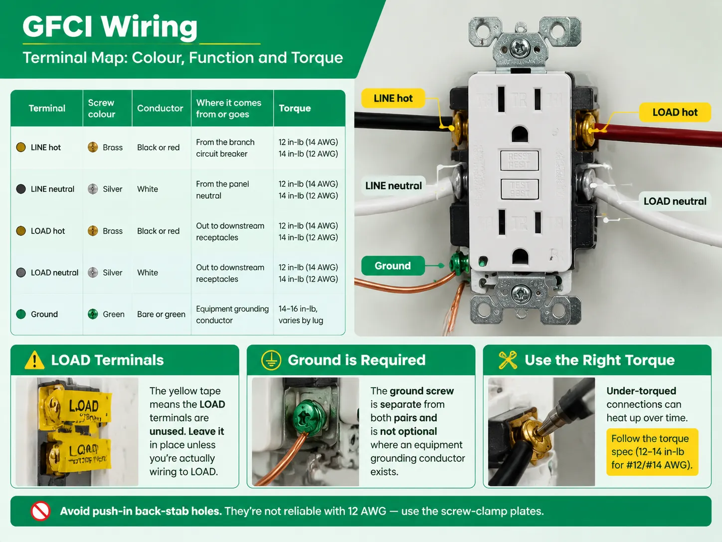
| Terminal | Screw colour | Conductor | Where it comes from or goes | Torque |
|---|---|---|---|---|
| LINE hot | Brass | Black or red | From the branch circuit breaker | 12 in-lb (14 AWG) / 14 in-lb (12 AWG) |
| LINE neutral | Silver | White | From the panel neutral | 12 in-lb (14 AWG) / 14 in-lb (12 AWG) |
| LOAD hot | Brass | Black or red | Out to downstream receptacles | 12 in-lb (14 AWG) / 14 in-lb (12 AWG) |
| LOAD neutral | Silver | White | Out to downstream receptacles | 12 in-lb (14 AWG) / 14 in-lb (12 AWG) |
| Ground | Green | Bare or green | Equipment grounding conductor | 14–16 in-lb, varies by lug |
Three points from this table stand out. First up, when the manufacturer ships LOAD connectors, they arrive with warning tape wrapped around them. Leaving the tape shows that the manufacturer has not used those LOAD connectors. In such a case, removing the tape before wiring does not help at all. Second, you need to know that the ground screw (for connecting the grounding wire of LOAD) is not coupled with the other pairs and is, therefore, not optional if you are using an equipment grounding conductor. Third, the torque values of GFCI connections are very important—if the GFCI connection is not tightened enough then it will heat up and may cause more problems than the wiring configuration.
One more wiring habit to avoid is the use of push-in back-stab holes in GFCI devices. While they may be included in some devices, they cannot be used if 12 AWG wire is being installed. They only work (if working at all) with wire smaller than 12 AWG.
| Wiring | What is protected | When it is the right answer |
|---|---|---|
| LINE only, LOAD left taped | This receptacle alone | A single wet location on a circuit that needs nothing else protected |
| LINE in, LOAD out to downstream receptacles | This receptacle plus everything downstream | A chain of kitchen counter outlets, a bathroom vanity run, several outdoor receptacles on one circuit |
| GFCI breaker at the panel | The entire branch circuit | 240 V equipment, or where no receptacle-style GFCI will fit |
| Two GFCIs on one run | Redundant | Generally not worth it — see the series wiring section below |
The feed-through feature is the main reason why only one GFCI is needed in the kitchen. A typical receptacle is much less expensive than a GFCI. Therefore, utilizing only one GFCI at the start of the line and several standard outlets is a more economical and efficient way of protecting the whole system than utilizing five GFCIs. The downside is that when the GFCI trips, it cuts off the entire system, causing some inconveniences, although it is not dangerous.
This is the major cause of all the callbacks, and the mechanism is such because it seems to be dependent on the generation of the device.
Modern devices: no power and reset. The latest GFCI outlets are made with the capability to detect reverse line-load errors in wiring, so if the wires are connected incorrectly to the load side of a device and power is fed incorrectly into the GFCI, it doesn’t work because it receives no power. That being the case, the outlet will not work at all and won’t keep its reset feature locked or going as well. This is not a defect, but rather a safety measure established by the producers of popular GFCI brands.
Older devices: they operate silently while providing no downstream protection. The other case that might happen is when the device seems to work normally and the test button of the device seems to work, however, in fact, it might not provide any downstream protection. This case is particularly dangerous because if someone believes that they have safety protection while using a device in a downstream outlet, they actually do not have any protection whatsoever.
Regardless of the specifics of the case at hand, the solution is the same, and takes no longer than couple of minutes.
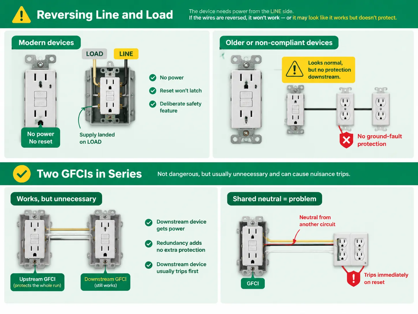
Installing a GFCI on the LOAD side of another GFCI is not a wiring mistake and is perfectly safe. It is simply unnecessary, and it can, sometimes, lead to false tripping.
There are three aspects to consider here. The downstream unit will work, as its own LINE terminals are supplied by the LOAD terminals of the upstream unit. So there is power and there is supply for the sensing circuit to operate. The redundancy is there, but it adds nothing, as the upstream device is already protecting the whole downstream run. And when trouble strikes the first device to trip usually becomes further from the problem.
There is a valid case when there is a neutral sharing issue. When the neutral of the downstream circuit comes from another source than the LOAD neutral of the GFCI serving it, the common case of multi-wire branches or rotting installations this circuit will act incorrectly. It will read the current coming through the transformer as the ground leakage. The effect is that the GFCI will trip immediately upon resetting even with no device connected. The solution is to make sure that the LINE and LOAD neutrals are separate.
Identifying the issue is the fundamental step which resolves the entire issue, and it requires a little time compared to wiring.
The sequence for a straightforward swap is the same as for any receptacle, and it is set out in this walkthrough of how to install a power outlet. What makes a GFCI different is only the second cable, so if the box has one cable, most of this article does not apply to your job.
A GFCI receptacle is noticeably deeper than the standard receptacle, approximately 1.75 inches deep on average. This fact alone is responsible for many installation errors.
A box that was designed for a standard duplex receptacle may not be adequately sized for a GFCI receptacle, especially when four conductors plus grounds are connecting to a feed-through GFCI receptacle. The deeper the GFCI receptacle is the more challenging it is to fold the conductors inside. An inadequately sized box can create a condition where the yoke is cracked or a termination is damaged, or a bare ground touches the LINE connections.
The calculation for cubic-inch volume of the box is provided in the NEC. The real-life formula will help to determine whether it is necessary at all to use a deeper box, box extensions, or to switch to an old-work box in each specific case. The requirements and how box volume is calculated are covered in this guide to choosing electrical boxes for outlets and switches. Checking the box before buying the device takes two minutes and saves a second trip.
Re-energise and check four voltages before the cover plate goes back on.
| Measurement | Expected | What a wrong reading means |
|---|---|---|
| Brass LINE to silver LINE | 114–126 V | No reading means no supply on LINE — check the miswire |
| Brass LINE to green ground | 114–126 V | Zero means an open ground |
| Silver LINE to green ground | 0–2 V | Around 120 V means a floating neutral or bootleg ground upstream |
| Downstream outlet hot to neutral, TEST pressed | 0 V | Live reading means the downstream cable is not on LOAD |
Next, conduct a mechanical test. Press TEST to observe what happens; assure that the device is triggered and the load points lose power. Then, press RESET to see whether everything comes back to normal. If the load points are protected, plug a testing device in one of them and then trip the GFCI switch again using the testing device.
One important diagnostic trick that you should know is that when there is no ground in the wiring, the plug-in three lights tester will not operate the GFCI, as the fault is created using the ground pin. In case of no ground present, rely on the TEST button of the device instead of the tester.
Feed-through protection has a labelling requirement that is compulsory.
According to NEC 406.4(D)(2), a grounding-type receptacle that is provided through GFCI protection on a circuit without grounding conductor must have stickers indicating that it is “GFCI Protected” and “No Equipment Ground”. Stickers are included in the packing that comes with GFCI device which eliminates the need to discard it until the work at the site is done.
However, when there is an equipment grounding conductor in the circuit, only the “GFCI Protected” sticker is required. Nevertheless, it still provides an important piece of information which allows realizing how protection works.
The primary purpose of LOAD is feed-through protection, but this is not always the proper application of it.
Nevertheless, it is advisable to use this option when you have a series of outlets placed in one wet area and one device protects all of them, which is like in the case of a kitchen counter.The arithmetic behind that decision looks at how many outlets a circuit can support and how they are used, which is the same reasoning covered in this look at how many outlets a 20 amp circuit can serve. One GFCI at the head of a chain is fine on load; it is the number of devices and their duty that matters.
Igoto makes wall switches, sockets, and receptacles for distributors, contractors, and OEM customers instead of manufacturing ready-made smart home systems. In North America, the collection consists of tamper-proof and weather-proof receptacles, standard and decorative switches as well as wall plates with the assistance of the relevant UL regulations.
The helpful aspect of this in case of GFCI installation is the elements surrounding the device. Feed-through options need a box of sufficient cubic inch capacity for deep devices and four conductors, a cover plate suitable for the new device yoke measurements and often in old houses a matching receptacle produced by the same manufacturer for subsequent outlet connections.Sourcing those together rather than in three orders is what the manufacturing programme is for, and the scope is set out on the wall switch and power outlet manufacturing page. What igoto does not do is install, inspect or certify an electrical installation — that belongs to a licensed electrician and the local authority having jurisdiction.
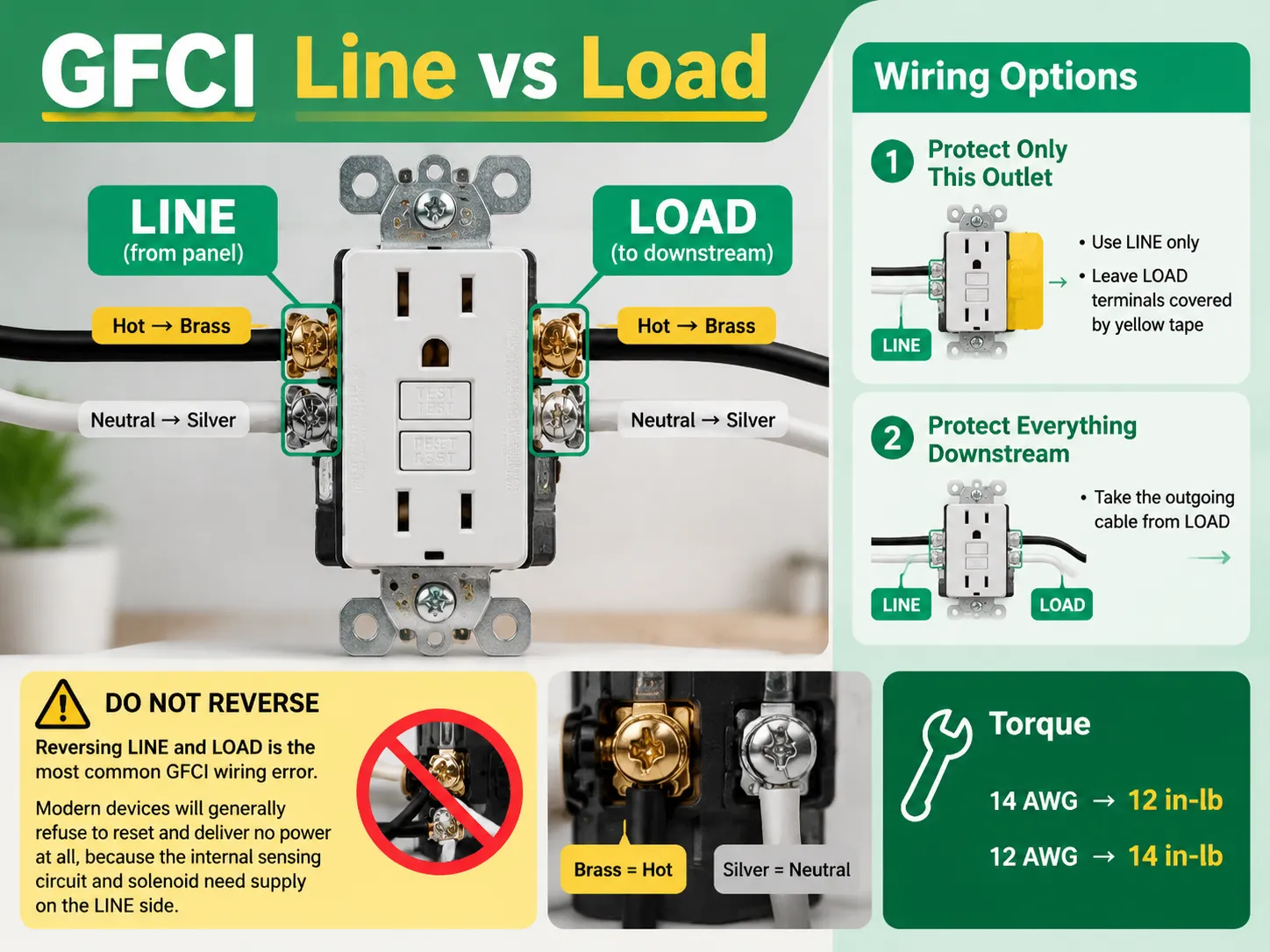
When talking about the LINE terminal, it brings current through the circuit breaker whereas LOAD terminal sends the power to all connected appliances. The live wire is connected to the brass connection and the neutral wire is connected to the silver terminal. The identification of the terminals can be seen on the back of the device as well as the LOAD terminal has yellow caution tape which needs to be removed after the downstream wiring is prepared. Don’t think about using vertical identification as it can vary from one model to another.
The supply terminals take the incoming current from the circuit breaker and the LOAD terminals send the current to the devices down the line. A hot wire is connected to the brass lug and the neutral wire is connected to the silver lug. The manufacturers identify the terminals at the back of the device; moreover, the LOAD terminal has a yellow caution tape indicating that it must be cut when the downstream cable is connected. It is important not to refer to the LOAD terminals as the identification may vary from one model to another.
The supply terminals receive electricity from the circuit breaker, while the LOAD terminals must deliver electric power to appliances further down in the circuit. A hot wire goes to the brass lug, while a neutral wire will connect to the silver lug. The manufacturers provide identification for the terminals at the back of the device; in addition, the LOAD terminal has a yellow caution tape that clearly warns about cutting it before connecting the cable running downstream. It is necessary to avoid using the term LOAD terminals, as this identification may differ in different models.
The LOAD terminals must be connected to those devices for the protection to be provided. A GFCI is supposed to protect itself and whatever outlets (receptacles) in which the line wires are connected to the GFCI LOAD terminals. If the downstream cable is connected to the LINE terminals instead, or if the downstream outlets are fed via a separate cable which hasn’t passed through the GFCI, the GFCI will not provide any protection. It’s easy to check: just press TEST and see whether the downstream outlet goes dead or not.
Absolutely, and you ought to do so in case you have nothing to protect downstream. The tape indicates that the terminals are not in use and removing it serves no purpose when one does not connect anything to the LOAD. If one replaces the two-prong receptacle with a GFCI outlet in a circuit with no ground wire, all of the new receptacles must be marked “GFCI Protected” and “No Equipment Ground”; these stickers are included in the package. Thus, it is advisable to keep the box until the termination of the job.
That is true. A GFCI uses a current transformer to compare the current in the hot and neutral wires, but it does not monitor the equipment grounding conductor. For this reason, the device offers good protection to people in an antiquated design that does not have any grounding at all, which is why such devices can be used as per NEC 406.4(D)(2), as long as they are marked “No Equipment Ground.” It is important to point out that it does not provide a ground path; therefore, the surge protectors plugged in cannot work.
Because brass will always serve as a hot wire and silver a neutral wire, the line and load wires should be properly connected. This rule applies to the remaining components discussed in this article.
Keep in mind the following when connecting devices: ensure that you are aware of the power supply to every device you will be plugging into a circuit; count the number of wires connected to your circuit (if you have only one wire then that will be the load wire, and there will be no protection downstream); do not allow neutral lines from both line and load circuits to short together, as this will cause GFCI devices to trip during reset; always conduct downstream outlet tests using GFCIs after tripping, as any outlet that becomes inactive during a trip will not receive downstream protection.
In summary, the above illustrates two terminals and one principle: Before connecting a device to a circuit, first connect the device(s) that it requires a power supply for to those terminals.
Two types of terminals can define how a GFCI outlet functions: One terminal is for an individual outlet and the other terminal can protect several outlets from a single GFCI outlet at the same cost. Using the appropriate terminal allows you to take advantage of the cost savings of using a single GFCI, while using […]

The housing types available in Doylestown date back to the 1800s, and this is also the main challenge you face when trying to buy a smart switch here. What you can use comes down to what is inside your wall box and not which brand you can trust the most. The guide shows you which […]

Of the very few areas of a house where the electrical code is crystal clear, the outlet located on the front porch is one such example. Since this area is outside, wet, and generally accessed through the doorway of the house, these elements trigger various requirements that have become quite stringent in the last two […]

 No.6 Tuozhan Road, Leshang Pioneer Park,Yueqingwan Bay Harbor,Yueqing city,Zhejiang Province


