

You are at the entrance of some steps, in darkness, unable to turn on the light until after reaching the top and flipping the switch. You either have to go up the stairs in utter darkness or head back to the light switch to turn on the lights. The simple solution is to have two light switches installed in the stairway to give the opportunity to turn the lights on while being at either end of the stairs. But what if you already have the switch installed and now you see three screws and don’t know which wire should go where? 3-way switch wiring is one of the most challenging jobs for many DIY enthusiasts. It is much more complicated than the use of a simple toggle switch because in the case of a simple toggle switch you know there is an “on” position while in the case of 3-way switches it’s not easy to understand how it works and what to do with the wires that connect the two switches.
This guide allows learning the process of wiring 3-way switch stepwise: how the circuit functions, which terminal performs a certain function, where each wire goes, how to do it from the scratch, what to do when something goes wrong, and when you should call an electrician for help.
In short, a 3-way switch is a switch that can turn a light on from two locations (for example top and bottom of stairs). It consists of two 3-way switches, each having a common (COM/C) terminal and two traveler terminals (L1/L2 or T1/T2). There are no markings for “on/off” on a 3-way switch because the meaning of the upward position of the switch depends on the position of the other switch.
A 3-way switch consists of three terminals which are used as a pair to turn on or off a single light from two different places. Contrary to the name, it does not refer to “three switches to operate one light” instead the two switches independently create an attractive working of “3-way control”. The term “3” is for three terminals through which this switch is used to operate.
In a given 3-way switch, electrical energy comes into the first switch’s common terminal. The common terminal can connect with one of the two traveler terminals but it cannot connect with both at the same time. The traveler terminal will connect to the common terminal of the second switch and the latter is going to connect to the bulb or light. Depending on which of the traveler connections is complete, the light may be switched either on or off. The other switch allows changing either of the travelers connected to the switch.
Every 3-way switch has the same anatomy, though labels vary by manufacturer:
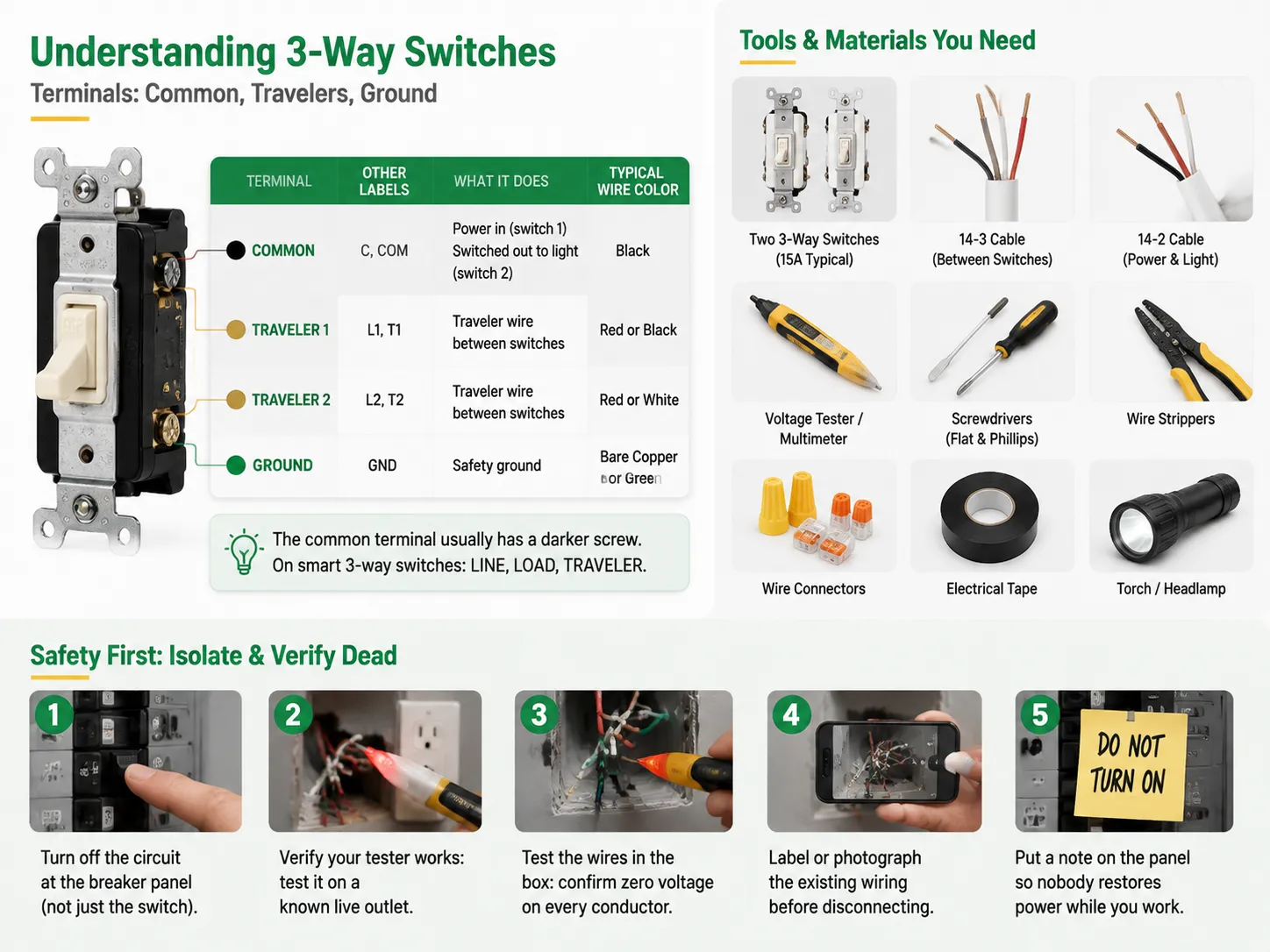
| Terminal | Other Labels | What It Does | Wire Color (Typical) |
|---|---|---|---|
| Common (COM) | C, black screw (darker screw) | The power input on switch 1; the switched output to the light on switch 2 | Black (hot) on switch 1; black (switched hot) on switch 2 |
| Traveler 1 | L1, T1, brass screw | One of two traveler wires linking the switches | Black or red (in 14-3 cable) |
| Traveler 2 | L2, T2, brass screw | The other traveler wire linking the switches | Red or white (in 14-3 cable) |
| Ground | GND, green screw | Safety ground; bonds to the box and switch | Bare copper or green |
The common terminal is generally indicated with a darker screw than the traveler’s screws, which serves as a recognizable sign. With a smart three-way switch, the terminals are usually marked as LINE, LOAD, and TRAVELER instead.
Do not skip this important step under any situation. Prior to handling any wires:
If you need to wire both switches from the very beginning either as a new circuit or total replacement, here are all the steps you need to follow.
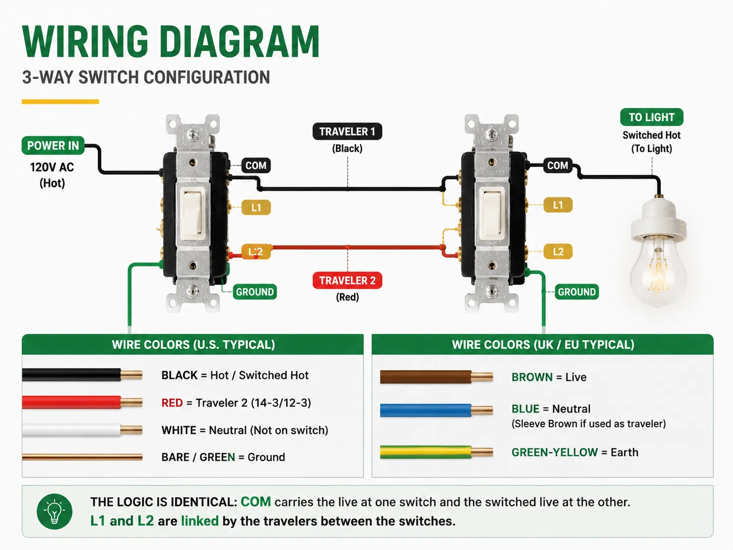
Here’s the layout in words (simplified diagram):
[Power in] --(black hot)--> Switch 1 [COM]
                             Switch 1 [L1] --(black traveler)--> Switch 2 [L1]
                             Switch 1 [L2] --(red traveler)--> Switch 2 [L2]
                                            Switch 2 [COM] --(black switched hot)--> Light
Wiring specifications in a regular USA installation are as follows: black conveying hot (or switched hot) current, red representing the second traveler (in 14-3/12-3 cable), white as neutral (kindly note that whites are interconnected internally, not in the switch), and bare wire/green for ground. In the case of the UK/EU, brown is taken to mean live, blue stands for neutral (but if it works as traveler/switch live, it is sleeved brown), and green-yellow indicates earth; additionally, the usual labels used in the terminals there are COM, L1, and L2 – COM leads live current from one switch and switched live current from another. The principle behind all of this remains more or less unchanged; however, it is essential to pay attention to the color specifications and labels.For a visual comparison of how different switch types are built, our guide to using dimmers vs standard switches on fans shows why terminal layouts differ between switch families.
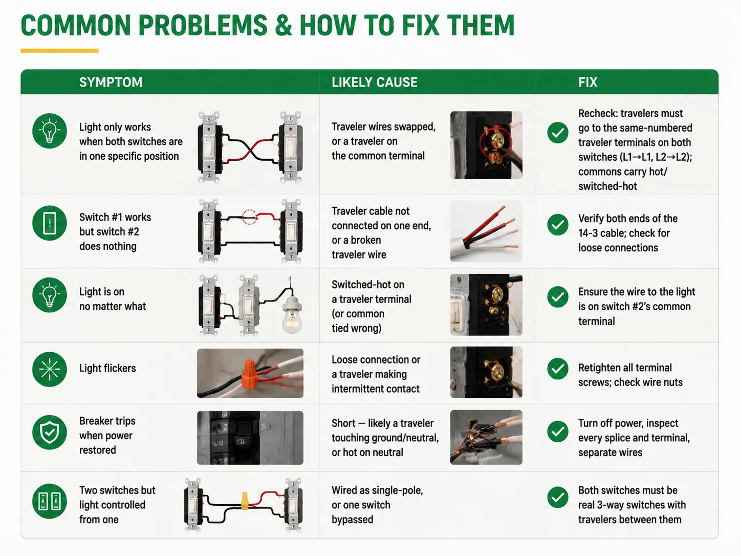
| Symptom | Likely Cause | Fix |
|---|---|---|
| Light only works when both switches are in one specific position | Traveler wires swapped, or a traveler on the common terminal | Recheck: travelers must go to the same-numbered traveler terminals on both switches (L1→L1, L2→L2); commons carry hot/switched-hot |
| Switch #1 works but switch #2 does nothing | Traveler cable not connected on one end, or a broken traveler wire | Verify both ends of the 14-3 cable; check for loose connections |
| Light is on no matter what | Switched-hot on a traveler terminal (or common tied wrong) | Ensure the wire to the light is on switch #2’s common terminal |
| Light flickers | Loose connection or a traveler making intermittent contact | Retighten all terminal screws; check wire nuts |
| Breaker trips when power restored | Short — likely a traveler touching ground/neutral, or hot on neutral | Turn off power, inspect every splice and terminal, separate wires |
| Two switches but light controlled from one | Wired as single-pole, or one switch bypassed | Both switches must be real 3-way switches with travelers between them |
There are two most frequently used methods for wiring the switches and they determine what goes into each box, as follows:
If you are simply replacing existing 3-way switches (not pulling new cable), the process is much simpler: take a picture of the old wiring, take it apart, and make the connections to the new switches in exactly the same way, ensuring that the common and traveler terminals are matched to those of the old switches. Most easy jobs fail because people think they are following the same wiring scheme; they are not.Before you buy replacements, it also helps to know whether you’re dealing with a single-pole or a true 3-way setup — our article on light dimmer vs fan switch differences explains how to read the terminal layout to tell switch types apart.
Smart 3-way switches offer application and voice control, but create wiring issues:
And if you’re deciding between a smart switch and a dimmer for a two-way setup, our guide to installing a dimmer switch walks through the wiring differences you’ll see on dimmer terminals compared with standard switches.
Although DIY is okay for straightforward 3-way installations, you should contact a licensed electrician if:
An electrician will be able to replace the 3-way switch in under an hour – very affordable for peace of mind knowing that the light from the staircase on the second floor won’t have the risk of fire.
The first switch has a hot (line) wire provided at the common terminal, which in a typical three-way switch may be marked COM or C and is represented by the darker screw of the switch. The other switch has the switched-hot wire going to the light connected at its common terminal. The two traveler terminals, which could either be marked L1/L2 or T1/T2 (depicted by brass screws), contain the two traveler wires; therefore, it is essential for the wires to connect the corresponding terminals at the two switch positions (i.e. L1 to L1, L2 to L2). Grounding must go to the green screw terminal. Remember the following rule: commons are responsible for carrying hot and switched-hot, while travelers are used for connecting the two switches.
Think of a pair of light switches that are linked through 2 “traveler” wires, much like two switches on a road that has two lanes. The electricity comes in via the common terminal of switch 1, which can send electricity through either traveler wire to switch 2 and the output to the light. Using either switch will flip the light on or off depending on the open traveler wire. This is the reason why 3 way switches do not come with markings for up or down: it will literally mean on or off depending on the other switch.
When someone incorrectly wires a 3-way switch, the most typical outcome is that the light operates only in certain positions of the switches — an indication that the travelers are incorrectly connected or one is connected to the common. Other kinds of mistakes may lead to the constant lighting of the fixture, flickering, and — in the event that a hot wire is in contact with a neutral or a ground wire — tripping the breaker or presenting hazards of electric shock or fire. Because 3-way circuits are live on both switch boxes, working with them while the power is on is actually quite risky.
“3 wire” typically signifies either that the switch comprises three terminals (it is a 3-way switch) or that a 3-wire cable (14-3/12-3 with black, red, white, and ground) is being used for the purposes of wiring. The following is how such wiring is done: First, connect the hot wire to the common terminal of switch 1; thereafter, run two traveler wires (from the two, one should be black, the other red from 14-3 cable) from the traveler terminals of both switches; connect wire from the light fixture to the common terminal of switch number 2; and finally connect all of the white neutrals of light and the switches. If the switch has four terminals, it is in fact a 4-way switch (in between two 3-way switches for added control) — connect all travelers with one pair and then the ones with the remaining pair.
Three-way switching may look simple and yet perplexing at the same time, especially for beginners. But as soon as you get what “the travelers connect the switches while commons carry hot and switched-hot”, everything becomes clear. There are 2 switches with 3 terminals each, a pair of traveler cables between them, and no ON/OFF signs since the meaning of their position depends on the other switch. The wiring can be done easily by an attentive DIYer: switch off the electricity, make sure it is not working, connect commons and travelers, connect all wires to the ground, and test the system from both ends.
In the case some problem occurs, the symptoms usually allow to find out what the trouble is: light works only at one switch position → travelers are swapped; one of the switches is not working properly → broken traveler connection; breaker goes off → short circuit must be checked right away. In case any problems come up like too old wiring or not having grounds or smart switches not giving you full understanding of the wiring system, it is better to contact an electrician.
If you’re sourcing quality 3-way and smart switches for a project in volume, IGOTO Electric manufactures wall switches, sockets, and smart wiring devices with CE/UKCA and other certifications — including models designed for two-way control — with OEM options for your own brand. For more on choosing between switch types, our guide to the different kinds of switches in electrical systems covers the full family.
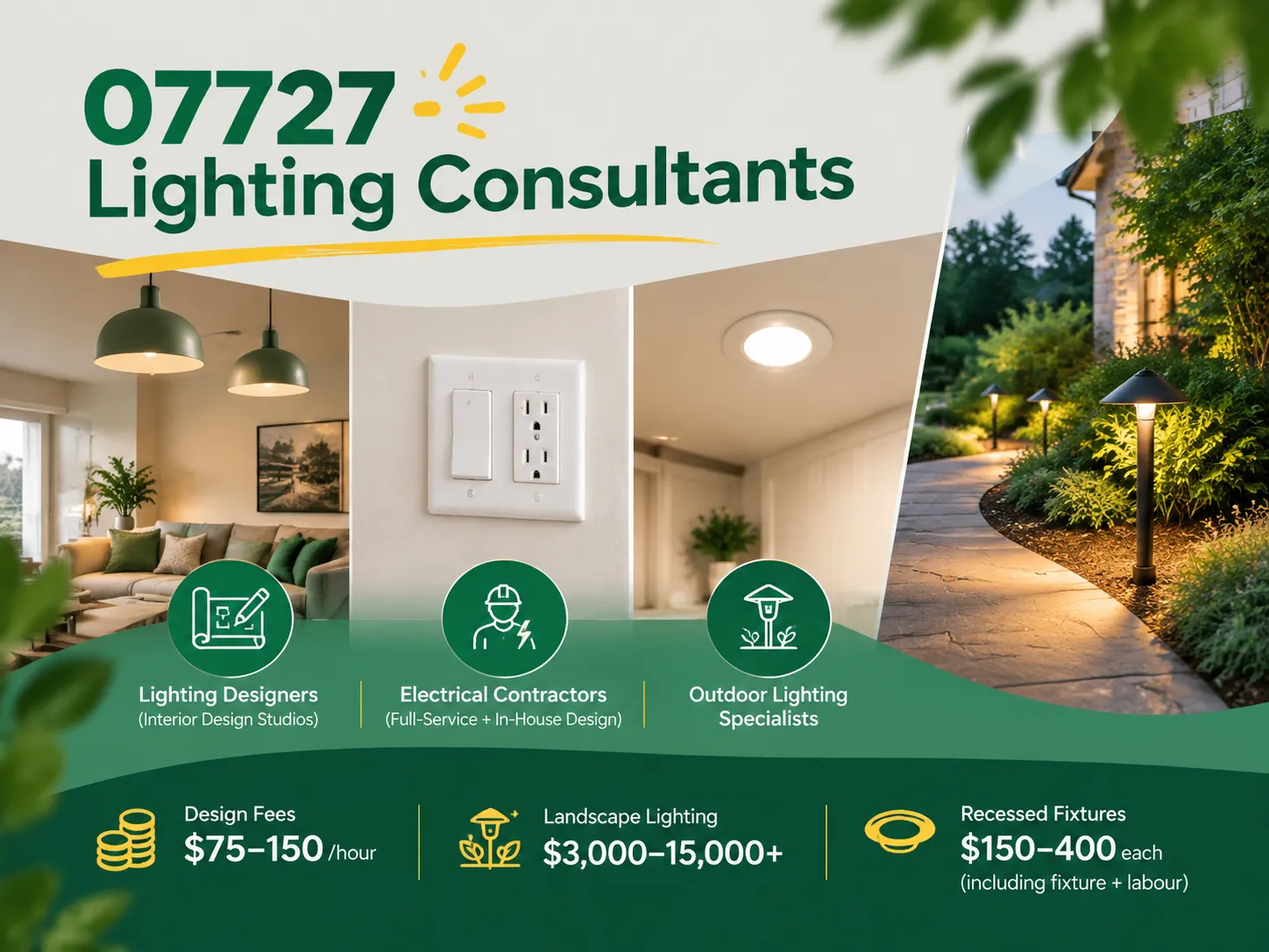
Farmingdale, along with parts of Wall Township and Tinton Falls, New Jersey, share the same zip code of 07727. Most of the houses built from the 1950s to the 1990s still exist today. Most of the homeowners are renovating their houses as opposed to building new homes. Homeowners tend to spend a lot more on […]

The term “07984 lighting consultants” gives people the impression that the five digits represent a postal code of some sort that indicates the place where lighting consultants provide services. This is, however, incorrect: there is no postal area coded 07984, which is only a code of mobile telecommunications in Great Britain. This means that the […]

San Francisco is not the average lighting control market. The housing stock is old and dense, and the electrical code does not allow for as many electrical installations as is allowed almost anywhere else in the U.S. Most homes that want complex lighting are Victorian or Edwardian buildings where no one wants to start opening […]

 No.6 Tuozhan Road, Leshang Pioneer Park,Yueqingwan Bay Harbor,Yueqing city,Zhejiang Province


